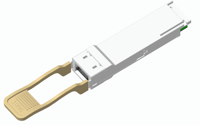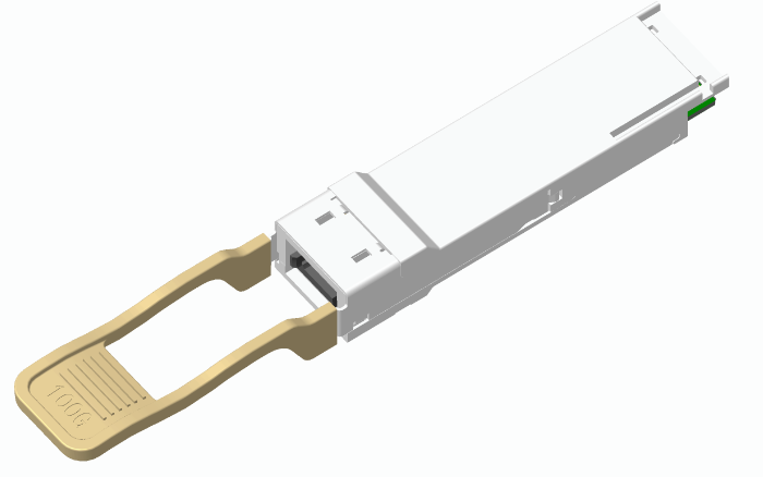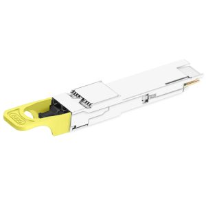
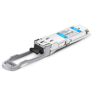

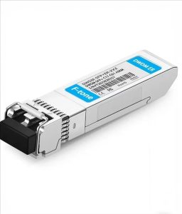
FTQ2-HG-SR4 是一款 100Gb/s QSFP28 SR4 光收发模块,采用 MPO 插座式光接口,四通道全双工并行传输,单通道速率最高 25.78 Gb/s。模块在 OM3 多模光纤上传输距离可达 70 m,OM4 上可达 100 m,功耗低于 2.2 W,内置数字诊断功能,适用于 100GBASE-SR4 以太网、数据中心内部互联与高速专有互连场景。
产品特点 / Product Features
- Hot Pluggable QSFP28 form factor
- MPO connector receptacle
- Four-channel full-duplex transceiver modules
- Transmission data rate up to 25.78Gb/s per channel
- Up to 70m on OM3 Multimode Fiber(MMF) and 100m on OM4 MMF
- Low power consumption <2.2W
- Operating case temperature 0Cto70C
- 3.3V power supply voltage
- RoHS 6 compliant
- Built-in digital diagnostic function
应用场景 / Applications
- IEEE 802.3bm 100GBASE SR4
- Proprietary High Speed Interconnections
- Data center
标准符合性 / Standards
- QSFP MSA
- SFF-8436 QSFP+
- SFF-8665
- SFF-8636
- Ethernet 100GBASE-SR4
技术参数 / Specifications
绝对最大额定值 / Absolute Maximum Ratings
| Parameter | Symbol | Min. | Max. | Unit | Note |
|---|---|---|---|---|---|
| Supply Voltage | Vcc | 0 | 3.6 | V | |
| Storage Temperature | Ts | -40 | 85 | °C | |
| Relative Humidity | RH | 5 | 85 | % |
推荐工作条件 / Recommended Operating Conditions
| Parameter | Symbol | Min. | Typ. | Max. | Unit | Note |
|---|---|---|---|---|---|---|
| Operating Case Temperature | Tc | 0 | 70 | °C | Commercial | |
| Power Supply Voltage | Vcc | 3.13 | 3.3 | 3.47 | V | |
| Power Supply Current | Icc | 0.65 | A |
发射端特性 / Transmitter Characteristics
| Parameter | Symbol | Min. | Typ. | Max. | Unit | Note | |
|---|---|---|---|---|---|---|---|
| Data Rate | DR | 25.78125 | Gb/s | ||||
| Center Wavelength | λC | 840 | 850 | 860 | nm | ||
| RMS Spectral Width | λRMS | 0.6 | nm | ||||
| Average Launch Power each lane | Pavg | -8.4 | +2.4 | dBm | |||
| Optical Modulation Amplitude (OMA)each lane | POMA | -6.4 | 3 | dBm | |||
| Difference in Launch Power between any two lanes |
Ptx,diff | 4 | dB | ||||
| Extinction Ratio | ER | 3 | dB | ||||
| Average Launch Power off each lane | Poff | -30 | dBm | ||||
| Transmitter Eye Mask Definition {X1, X2, X3, Y1, Y2, Y3} |
{0.3, 0.38, 0.45, 0.35, 0.41, 0.5} | Hit Ratio = 5×10⁻⁵ |
|||||
| Input Differential Impedance | ZIN | 100 | Ω | ||||
| Data Input Swing Differential | VINPP | 300 | 1000 | mV | |||
接收端特性 / Receiver Characteristics
| Parameter | Symbol | Min. | Typ. | Max. | Unit | Note |
|---|---|---|---|---|---|---|
| Data rate per Lane | BR | 25.78125 | Gb/s | |||
| Damage Threshold | THd | 3 | dBm | |||
| Average receiver power, each lane | – | -10.3 | 2.4 | dBm | ||
| Receiver Sensitivity in OMA, each Lane | SEN | -5.2 | dBm | 1 | ||
| LOS De-Assert | LOSD | -10 | dBm | |||
| LOS Assert | LOSA | -30 | dBm | |||
| LOS Hysteresis | LOSH | 0.5 | 6 | dB | ||
| Data Output Swing Differential | VOUTPP | 500 | 800 | mV | ||
| LOS Fault | – | 2.0 | Vcc | V | ||
| LOS Normal | – | 0 | 0.8 | V |
Note: 1. Measured with a PRBS 2^31-1 test pattern, @25.78125Gb/s, BER@5E-5
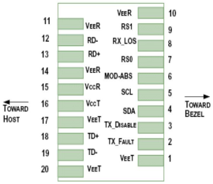
引脚排列图 / Pin-out Drawing
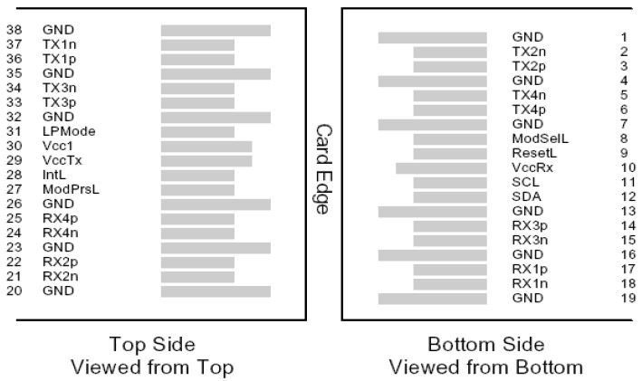
引脚定义 / Pin Description
| Pin | Logic | Symbol | Description | Note |
|---|---|---|---|---|
| 1 | GND | Ground | ||
| 2 | CML-I | Tx2n | Transmitter Inverted Data Input | |
| 3 | CML-I | Tx2p | Transmitter Non-Inverted Data Output | |
| 4 | GND | Ground | ||
| 5 | CML-I | Tx4n | Transmitter Inverted Data Input | |
| 6 | CML-I | Tx4p | Transmitter Non-Inverted Data Output | |
| 7 | GND | Ground | ||
| 8 | LVTLL-I | ModSelL | Module Select | |
| 9 | LVTLL-I | ResetL | Module Reset | |
| 10 | VccRx | +3.3VPowerSupplyReceiver | ||
| 11 | LVCMOS-I/O | SCL | 2-WireSerialInterfaceClock | |
| 12 | LVCMOS-I/O | SDA | 2-WireSerialInterfaceData | |
| 13 | GND | Ground | ||
| 14 | CML-O | Rx3p | Receiver Non-Inverted Data Output | |
| 15 | CML-O | Rx3n | Receiver Inverted Data Output | |
| 16 | GND | Ground | ||
| 17 | CML-O | Rx1p | Receiver Non-Inverted Data Output | |
| 18 | CML-O | Rx1n | Receiver Inverted Data Output | |
| 19 | GND | Ground | ||
| 20 | GND | Ground | ||
| 21 | CML-O | Rx2n | Receiver Inverted Data Output | |
| 22 | CML-O | Rx2p | Receiver Non-Inverted Data Output | |
| 23 | GND | Ground | ||
| 24 | CML-O | Rx4n | Receiver Inverted Data Output | |
| 25 | CML-O | Rx4p | Receiver Non-Inverted Data Output | |
| 26 | GND | Ground | ||
| 27 | LVTTL-O | ModPrsL | Module Present | |
| 28 | LVTTL-O | IntL | Interrupt Output | |
| 29 | VccTx | +3.3VPowerSupplytransmitter | ||
| 30 | Vcc1 | +3.3VPowerSupply | ||
| 31 | LVTTL-I | LPMode | Low Power Mode | |
| 32 | GND | Ground | ||
| 33 | CML-I | Tx3p | Transmitter Non-Inverted DataInput | |
| 34 | CML-I | Tx3n | Transmitter Inverted Data Output | |
| 35 | GND | Ground | ||
| 36 | CML-I | Tx1p | Transmitter Non-Inverted Data Input | |
| 37 | CML-I | Tx1n | Transmitter Inverted Data Output | |
| 38 | GND | Ground |
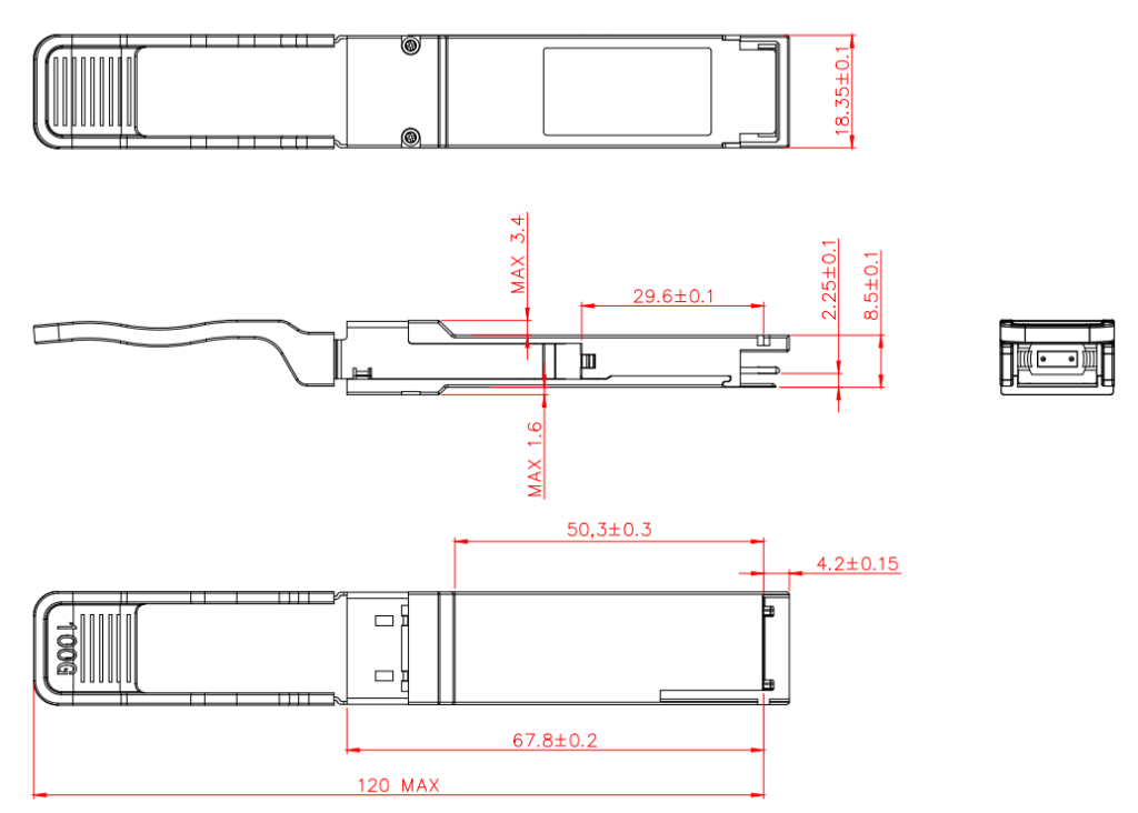
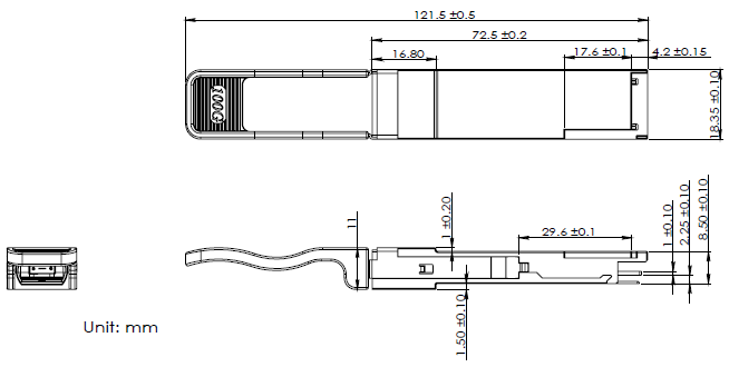
封装尺寸 / Package Outline
Note: There are two kinds of Latch colour, colour number7402U and colour number 475U.
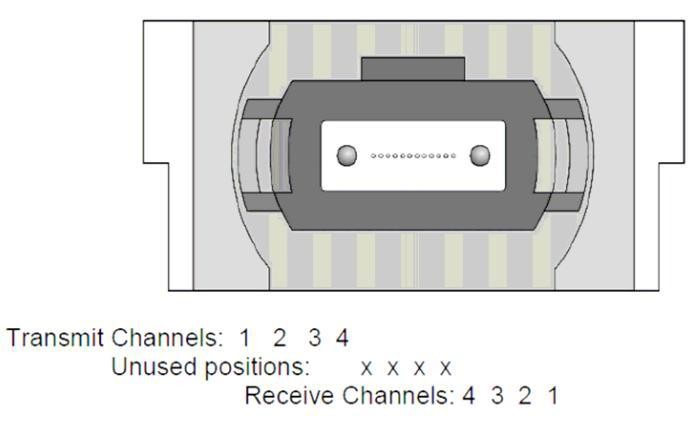
光接口通道分配 / Optical Interface Lanes and Assignment
The optical interface port is a male MPO connector. The four fiber positions on the left as shown in Figure 2, with the key up, are used for the optical transmit signals (Channel 1 through4). The fiber positions on the right are used for the optical receive signals (Channel 4 through 1). The central four fibers are physically present.
数字诊断监控接口 / Digital Diagnostic Monitoring Interface
| Parameter | Symbol | Accuracy | Calibration | Note |
|---|---|---|---|---|
| Temperature | DMI_Temp | ±3°C | Internal | Over operating temp |
| Voltage | DMI _VCC | ±0.1V | Internal | Full operating range |
| Bias Current | DMI_BIAS | ±10% | Internal | Per channel |
| TX Power | DMI_TX | ±3 dB | Internal | Per channel |
| RX Power | DMI_RX | ±3 dB | Internal | Per channel |
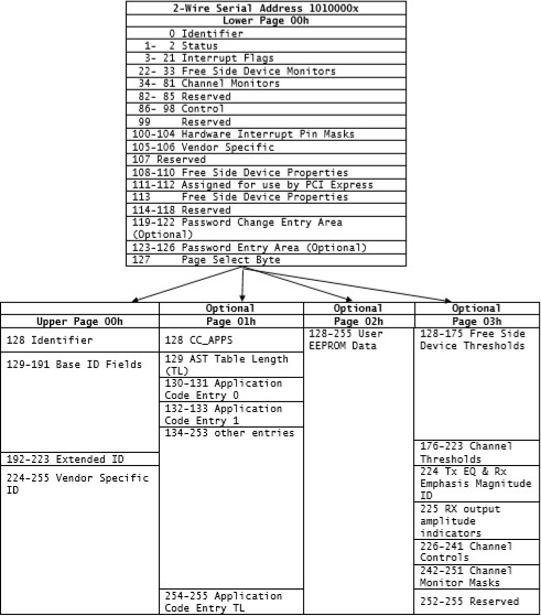
EEPROM 信息 / EEPROM Information
1、105/106 初始化 / Initialization
| Page | Address | Bit | Value | |
|---|---|---|---|---|
| Lower page 00h | 105 | 7:0 | 01h | |
| Lower page 00h | 106 | 7:0 | 1Fh |
2、LP 模式 / LP Mode
| Page | Address | Bit | Description | Description |
|---|---|---|---|---|
| Lower page 00h | 93 | 1:0 | LPMode Select | Default:00h 03h:Low Power Mode 01h:High Power Mode |
3、EQ/EM/AM/SQ 关闭 / EQ/EM/AM/SQ Disable
| Page | Address | Bit | Description | Description |
|---|---|---|---|---|
| 03 | 226 | 0 | EQ Mode Select | Default:0 0:EQ is controlled by Page 3 Addr 234/235 1:Auto-adaption EQ |
| 234 | 7:4 | Tx1 EQ | Default:66h Every channel range :0~10 | |
| 3:0 | Tx2 EQ | |||
| 235 | 7:4 | Tx3 EQ | ||
| 3:0 | Tx4 EQ | |||
| 03 | 236 | 7:4 | Rx1 EM | SR default:22h(Rx1/Rx2/Rx3/Rx4 EMall are 2) Every channel range:0~7 |
| 3:0 | Rx2 EM | |||
| 237 | 7:4 | Rx3 EM | ||
| 3:0 | Rx4 EM | |||
| 03 | 238 | 7:4 | Rx1 AM | Default:22h(Rx1/Rx2/Rx3/Rx4 AMall are 2) Every channel range:0~3 |
| 3:0 | Rx2 AM | |||
| 239 | 7:4 | Rx3 AM | ||
| 3:0 | Rx4 AM | |||
| 03 | 240 | 7 | Rx4 SQ Disable | Default:1 0:Enable SQ,Tx Power is -40dBm 1:Disable SQ |
| 6 | Rx3 SQ Disable | |||
| 5 | Rx2 SQ Disable | |||
| 4 | Rx1 SQ Disable | |||
| 3 | Tx4 SQ Disable | |||
| 2 | Tx3 SQ Disable | |||
| 1 | Tx2 SQ Disable | |||
| 0 | Tx1 SQ Disable |
4、写入并保存 Page 00/01/02/03 数据
| Page | Address | Bit | Description | Description |
|---|---|---|---|---|
| 05 | 128~131 | Customer Password :PW1 PW2 PW3 PW4 | Default:00h 00h 10h 11h |
| Method 1 (Write the project password firstly) | ||||
|---|---|---|---|---|
| Write 00h/00h/10h/11h to addr 123/124/125/126 separately, and then change the data of the selected page |
||||
| Method 2 (Write the customer password firstly) | ||||
| Write the customer password PW1 PW2 PW3 PW4 to addr 123/124/125/126 separately, and then change the data of the selected page. |
||||
| 5、Change customer password method | ||||
| Method 1 (Write project password firstly) | ||||
| 1)Write Addr 123 = 0; | ||||
| 2)Write Addr 124 = 0; | ||||
| 3)Write Addr 125 = 10h; | ||||
| 4)Write Addr 126 = 11h; | ||||
| 5)Write Addr 127 = 05h; | ||||
| 6)Write Addr 128 = NEW PW1; | ||||
| 7)Write Addr 129 = NEW PW2; | ||||
| 8)Write Addr 130 = NEW PW3; | ||||
| 9)Write Addr 131 = NEW PW4. | ||||
| Method 2 (Write customer password firstly) | ||||
| 1)Write Addr 123 = PW1; | ||||
| 2)Write Addr 124 = PW2; | ||||
| 3)Write Addr 125 = PW3; | ||||
| 4)Write Addr 126 = PW4; | ||||
| 5)Write Addr 119 = NEW PW1; | ||||
| 6)Write Addr 120 = NEW PW2; | ||||
| 7)Write Addr 121= NEW PW3; | ||||
| 8)Write Addr 122= NEW PW4. | ||||
Upper Page 00h 寄存器映射
| Data Address (D/H) | Bytes Contents | Description of field |
|---|---|---|
| 128 / 80h | 11h | Identifier |
| 129 / 81h | 8Ch | Ext.Identifier |
| 130 / 82h | 0Ch | Connector |
| 131 / 83h | 80h | Specification compliance (8bytes) |
| 132 / 84h | 00h | SONET Compliance codes |
| 133 / 85h | 00h | SAS/SATA compliance codes |
| 134 / 86h | 00h | Gigabit Ethernet Compliant codes |
| 135 / 87h | 40h | Fibre Channel link length |
| 136 / 88h | 00h | |
| 137 / 89h | 02h | Fibre Channel transmission media |
| 138 / 8Ah | 02h | Fibre Channel Speed |
| 139 / 8Bh | 03h | Encoding |
| 140 / 8Ch | FFh | BR, Normal, 25.78Gb,units of 100 Mb/sec |
| 141 / 8Dh | 00h | Extended rateselect Compliance |
| 142 / 8Eh | 00h | Length(SMF) |
| 143 / 8Fh | 23h | Length(OM3 50 um) |
| 144 / 90h | 00h | Length(OM2 50um) |
| 145 / 91h | 00h | Length(OM1 62.5 um) |
| 146 / 92h | 32h | Length(Copper or OM4 50um) |
| 147 / 93h | 00h | Device tech |
| 148 / 94h | 4Fh | Vendor name: O |
| 149 / 95h | 45h | E |
| 150 / 96h | 4Dh | M |
| 151 / 97h | 20h | Vendor name: Blank (ASCII) |
| 152 / 98h | 20h | Vendor name: Blank (ASCII) |
| 153 / 99h | 20h | Vendor name: Blank (ASCII) |
| 154 / 9Ah | 20h | Vendor name: Blank (ASCII) |
| 155 / 9Bh | 20h | Vendor name: Blank (ASCII) |
| 156 / 9Ch | 20h | Vendor name: Blank (ASCII) |
| 157 / 9Dh | 20h | Vendor name: Blank (ASCII) |
| 158 / 9Eh | 20h | Vendor name: Blank (ASCII) |
| 159 / 9Fh | 20h | Vendor name: Blank (ASCII) |
| 160/ A0h | 20h | Vendor name: Blank (ASCII) |
| 161 / A1h | 20h | Vendor name: Blank (ASCII) |
| 162 / A2h | 20h | Vendor name: Blank (ASCII) |
| 163 / A3h | 20h | Vendor name: Blank (ASCII) |
| 164 / A4h | 10h | Extended Module |
| 165 / A5h | 00h | Vendor OUI |
| 166 / A6h | 00h | |
| 167 / A7h | 00h | |
| 168 / A8h | 31h | (ASCII) P/N:100G-SR4 |
| 169 / A9h | 30h | (ASCII) |
| 170 / AAh | 30h | (ASCII) |
| 171 / ABh | 47h | (ASCII) |
| 172 / ACh | 20h | (ASCII) |
| 173 / ADh | 53h | (ASCII) |
| 174 / AEh | 52h | (ASCII) |
| 175 / AFh | 34h | (ASCII) |
| 176 / B0h | 20h | (ASCII) |
| 177 / B1h | 20h | (ASCII) |
| 178 / B2h | 20h | (ASCII) |
| 179 / B3h | 20h | (ASCII) |
| 180 / B4h | 20h | Blank (ASCII) |
| 181 / B5h | 20h | Blank (ASCII) |
| 182 / B6h | 20h | Blank (ASCII) |
| 183 / B7h | 20h | Blank (ASCII) |
| 184 / B8h | 30h | Vendor rev_01 |
| 185 / B9h | 31h | |
| 186 / BAh | 42h | Wavelength:850nm |
| 187 / BBh | 68h | |
| 188 / BCh | 07h | Wavelength tolerance |
| 189 / BDh | D0h | |
| 190 / BEh | 46h | Max case temp. |
| 191 / BFh | 4Eh | CC_BASE_128 to 190 |
| 192 / C0h | 02h | Options (4bytes) |
| 193 / C1h | 07h | |
| 194 /C2h | FAh | |
| 195 / C3h | DAh | |
| 196 / C4h | 20h | Vendor SN (16bytes) |
| 197 / C5h | 20h | |
| 198 / C6h | 20h | |
| 199 / C7h | 20h | |
| 200 / C8h | 20h | |
| 201 / C9h | 20h | |
| 202 / CAh | 20h | |
| 203 / CBh | 20h | |
| 204 / CCh | 20h | |
| 205 / CDh | 20h | |
| 206 / CEh | 20h | |
| 207 / CFh | 20h | |
| 208 / D0h | 20h | |
| 209 / D1h | 20h | |
| 210 / D2h | 20h | |
| 211 / D3h | 20h | |
| 212 / D4h | 20h | Date Code (8bytes) |
| 213 / D5h | 20h | |
| 214 / D6h | 20h | |
| 215 / D7h | 20h | |
| 216 / D8h | 20h | |
| 217 / D9h | 20h | |
| 218 / DAh | 20h | Lot code |
| 219 / DBh | 20h | |
| 220 / DCh | 0Ch | Diagnostic Monitoring Type |
| 221 / DDh | 00h | Enhanced Options |
| 222 / DEh | 67h | EXTENDED BIT RATE |
| 223 / DFh | — | CC_EXT_192 to 222 |
| 224 / E0h | — | Vendor Specific (Address 224-255) |
| 225 / E1h | — | |
| 226 / E2h | — | |
| 227 / E3h | — | |
| 228 / E4h | — | |
| 229 / E5h | — | |
| 230 / E6h | — | |
| 231 / E7h | — | |
| 232 / E8h | — | |
| 233 / E9h | — | |
| 234 / EAh | — | |
| 235 / EBh | — | |
| 236 / ECh | — | |
| 237 / EDh | — | |
| 238 / EEh | — | |
| 239 / EFh | — | |
| 240 / F0h | — | |
| 241 / F1h | — | |
| 242 / F2h | — | |
| 243 / F3h | — | |
| 244 / F4h | — | |
| 245 / F5h | — | |
| 246 / F6h | — | |
| 247 / F7h | — | |
| 248 / F8h | — | |
| 249 / F9h | — | |
| 250 / FAh | — | |
| 251 / FBh | — | |
| 252 / FCh | — | |
| 253 / FDh | — | |
| 254 / FEh | — | |
| 255 / FFh | — |
订购信息 / Ordering Information
| Part Number | Product Description |
|---|---|
| FTQ2-HG-SR4 | QSFP28 Transceiver, 100Gb/s, SR4, with DDM, 0Cto70C |
地区:中国四川天府新区
服务区域:全球
联系方式:
企业电话:028-85255257 | 企业传真:028-85977702 | 企业手机:19081343401
Site:https://www.f-tone.com
人事部:hr@f-tone.com | 市场部:sales@f-tone.com | 技术支持:support@f-tone.com
本产品为100G QSFP28 SR4光模块产品线,详细信息,请联系我们的销售人员,谢谢!
Important Notice
Performance figures, data and any illustrative material provided in this data sheet are typical and must be specifically confirmed in writing by F-tone Networks before they become applicable to any particular order or contract. In accordance with the F-tone Networks policy of continuous improvement specifications may change without notice. The publication of information in this data sheet does not imply freedom from patent or other protective rights of F-tone Networks or others. Further details are available from any F-tone Networks sales representative.