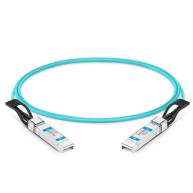
25G SFP28 to SFP28 Active Optical Cable
FTCS-25G-S28-Oxxx
PRODUCT FEATURES
- Up to 28Gbps Data rate per channel
- Maximum link length of 100m links on OM3 multimode fiber
- High Reliability 850nm VCSEL technology
- Electrically hot-pluggable
- Electrical interface compliant to SFF-8431
- Case operating temperature range:0°C to 70°C
- Power dissipation < 1.0W per cable end
APPLICATIONS
- 25G Ethernet
- Data center and Fiber channel
STANDARD
- Compliant to SFF-8431
- Compliant to SFF 8472
- RoHS Compliant.
Absolute Maximum Ratings
|
Parameter |
Symbol |
Min. |
Typ. |
Max. |
Unit |
Note |
|
Storage Temperature |
Ts |
-40 |
– |
85 |
ºC |
|
|
Relative Humidity |
RH |
5 |
– |
95 |
% |
|
|
Power Supply Voltage |
VCC |
-0.3 |
– |
4 |
V |
|
|
Signal Input Voltage |
Vcc-0.3 |
– |
Vcc+0.3 |
V |
Recommended Operating Conditions
|
Parameter |
Symbol |
Min. |
Typ. |
Max. |
Unit |
Note |
|
Case Operating Temperature |
Tcase |
0 |
– |
70 |
ºC |
Without air flow |
|
Power Supply Voltage |
VCC |
3.14 |
3.3 |
3.46 |
V |
|
|
Power Supply Current |
ICC |
– |
300 |
mA |
per cable end |
|
|
Data Rate |
BR |
25.78 |
Gbps |
General Product Characteristics
|
Parameter |
Value |
Unit |
Notes |
|
Module Form Factor |
SFP+ |
||
|
Maximum Data Rate |
28 |
Gb/s |
|
|
Standard Cable Lengths |
3, 5, 7, 10, 50, 100 |
meters |
Other lengths may be available upon request (<= 100m OM3) |
|
Protocols Supported |
Typical applications include InfiniBand, Fiber Channel, 25G Ethernet |
||
|
Electrical Interface and Pin-out |
20-pin edge connector |
Pin-out as defined by the SFP+ MSA |
|
|
Standard Optical Cable Type |
Multimode ribbon fiber cable assembly |
||
|
Maximum Power Consumption per End |
1.0 |
W |
per cable end |
|
Management Interface |
Serial, I2C-based, 400 kHz maximum frequency |
As defined by the SFP+ MSA |
Note:
Low rate is 24~26Gb/s & High rate is 25~28Gb/s, different rate range has different register setting, not auto-Negotiation
Electrical Characteristics
|
Parameter |
Symbol |
Min |
Typ |
Max |
Unit |
NOTE |
|
Supply Voltage |
VccT, VccR |
3.14 |
3.3 |
3.46 |
V |
|
|
Supply Current |
Icc |
300 |
mA |
|||
|
Transmitter |
||||||
|
Differential data input swing |
Vin,pp |
50 |
900 |
mV |
1 |
|
|
Single ended input voltage tolerance |
VinT |
-0.3 |
4.0 |
V |
||
|
Receiver |
||||||
|
Differential data output swing |
Vout,pp |
300 |
850 |
mV |
2 |
|
|
Single-ended output voltage |
-0.3 |
4.0 |
V |
Notes:
- AC coupled internally. Self-biasing 100Ω differential input.
- AC coupled with 100Ω differential output impedance.
Optical and Electrical Characteristics
|
Parameter |
Symbol |
Min |
Typical |
Max |
Unit |
Notes |
||
|
Transmitter |
||||||||
|
Data rate |
BR |
25.78 |
Gbps |
|||||
|
Centre Wavelength |
λc |
840 |
850 |
860 |
nm |
|||
|
Spectral Width (-20dB) |
σ |
0.6 |
nm |
|||||
|
Average Output Power |
Pavg |
-8.4 |
2.4 |
dBm |
||||
|
Optical Power OMA |
POMA |
-6.4 |
3 |
dBm |
||||
|
Extinction Ratio |
ER |
2 |
dB |
|||||
|
Differential data input swing |
VIN,PP |
40 |
1000 |
mV |
||||
|
Input Differential Impedance |
ZIN |
90 |
100 |
110 |
Ω |
|||
|
TX Disable |
Disable |
2.0 |
Vcc |
V |
||||
|
Enable |
0 |
0.8 |
V |
|||||
|
TX Fault |
Fault |
2.0 |
Vcc |
V |
||||
|
Normal |
0 |
0.8 |
V |
|||||
|
Receiver |
||||||||
|
Data rate |
BR |
25.78 |
Gbps |
|||||
|
Centre Wavelength |
λc |
840 |
850 |
860 |
nm |
|||
|
Receiver Sensitivity (OMA) |
Psens |
– |
– |
-10 |
dBm |
|||
|
Stressed Sensitivity (OMA) |
– |
– |
-5.2 |
dBm |
||||
|
Receiver Power (OMA) |
3 |
dBm |
||||||
|
LOS De-Assert |
LOSD |
-13 |
dBm |
|||||
|
LOS Assert |
LOSA |
-30 |
dBm |
|||||
|
LOS Hysteresis |
0.5 |
dB |
||||||
|
Differential data output swing |
Vout,PP |
300 |
850 |
mV |
||||
|
LOS |
High |
2.0 |
Vcc |
V |
||||
|
Low |
0.8 |
V |
||||||
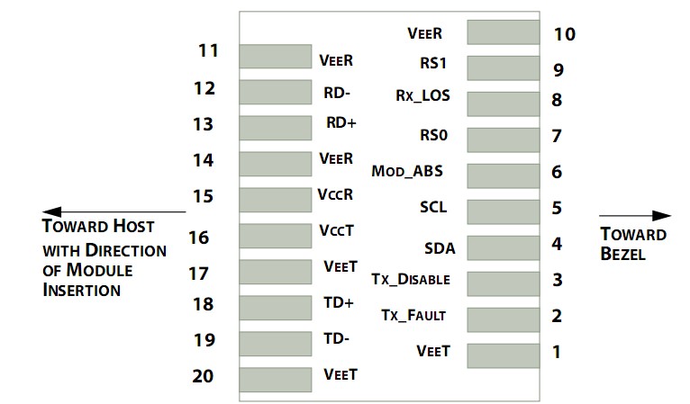
Pin Assignment
|
Pin |
Symbol |
Name/Description |
NOTE |
|
1 |
VEET |
Transmitter Ground (Common with Receiver Ground) |
1 |
|
2 |
TFAULT |
Transmitter Fault. |
2 |
|
3 |
TDIS |
Transmitter Disable. Laser output disabled on high or open. |
3 |
|
4 |
SDA |
2-wire Serial Interface Data Line |
4 |
|
5 |
SCL |
2-wire Serial Interface Clock Line |
4 |
|
6 |
MOD_ABS |
Module Absent. Grounded within the module |
4 |
|
7 |
RS0 |
Rate Select 0 |
5 |
|
8 |
LOS |
Loss of Signal indication. Logic 0 indicates normal operation. |
6 |
|
9 |
RS1 |
No connection required |
1 |
|
10 |
VEER |
Receiver Ground (Common with Transmitter Ground) |
1 |
|
11 |
VEER |
Receiver Ground (Common with Transmitter Ground) |
1 |
|
12 |
RD- |
Receiver Inverted DATA out. AC Coupled |
|
|
13 |
RD+ |
Receiver Non-inverted DATA out. AC Coupled |
|
|
14 |
VEER |
Receiver Ground (Common with Transmitter Ground) |
1 |
|
15 |
VCCR |
Receiver Power Supply |
|
|
16 |
VCCT |
Transmitter Power Supply |
|
|
17 |
VEET |
Transmitter Ground (Common with Receiver Ground) |
1 |
|
18 |
TD+ |
Transmitter Non-Inverted DATA in. AC Coupled. |
|
|
19 |
TD- |
Transmitter Inverted DATA in. AC Coupled. |
|
|
20 |
VEET |
Transmitter Ground (Common with Receiver Ground) |
1 |
Notes:
- Circuit ground is internally isolated from chassis ground.
- TFAULT is an open collector/drain output, which should be pulled up with a 4.7k – 10k Ohms resistor on the host board if intended for use. Pull up voltage should be between 2.0V to Vcc + 0.3V.A high output indicates a transmitter fault caused by either the TX bias current or the TX output power exceeding the preset alarm thresholds. A low output indicates normal operation. In the low state, the output is pulled to <0.8V.
- Laser output disabled on TDIS >2.0V or open, enabled on TDIS <0.8V.
- Should be pulled up with 4.7kΩ- 10kΩ host board to a voltage between 2.0V and 3.6V. MOD_ABS pulls line low to indicate module is plugged in.
- Internally pulled down per SFF-8431 Rev 4.1.
- LOS is open collector output. It should be pulled up with 4.7kΩ – 10kΩ on host board to a voltage between 2.0V and 3.6V. Logic 0 indicates normal operation; logic 1 indicates loss of signal.
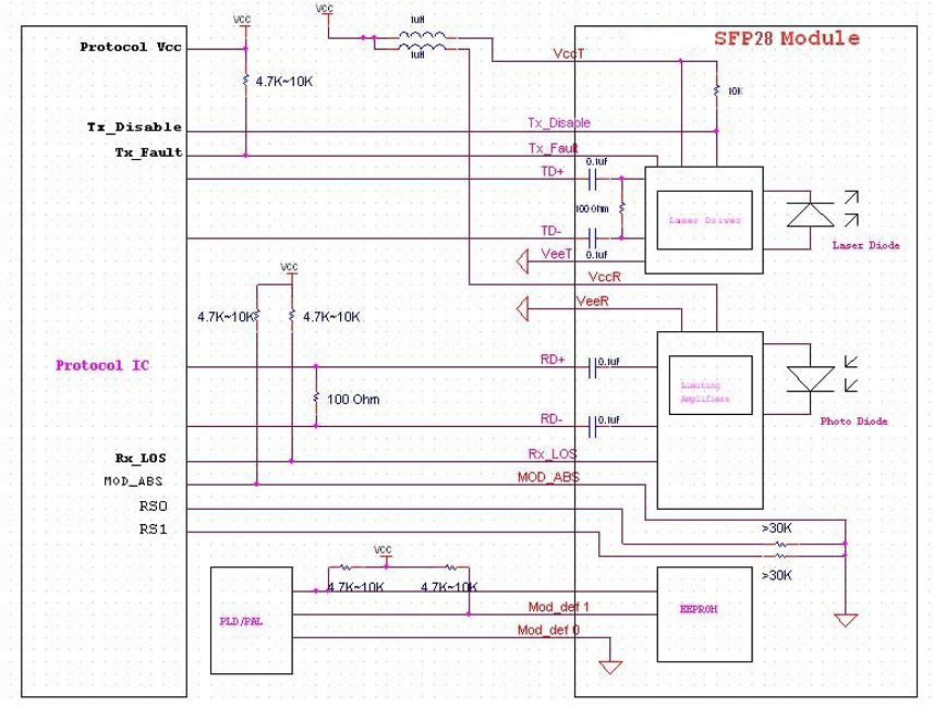
Host – Transceiver Interface Block Diagram
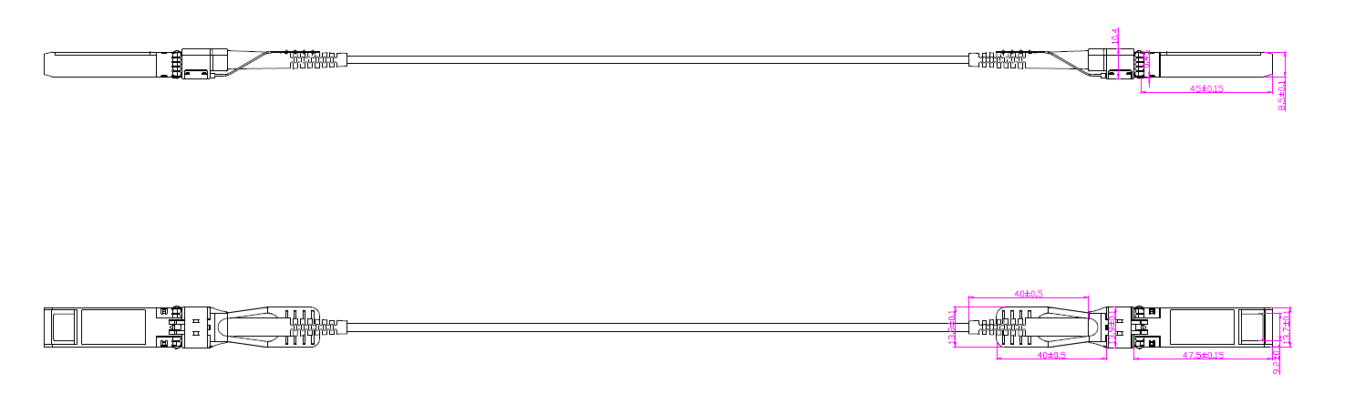
Outline Dimensions
Product selection
|
Part Number |
Product description |
|
FTCS-25G-S28-Oxxx |
SFP28 to SFP28 , 25G, 100m, Active Optical Cable, 0°C~+70°C |
Note:
- Cable length =<100m
- More detail product selection and cable lengths,please contact sales
Important Notice
Performance figures, data and any illustrative material provided in this data sheet are typical and must be specifically confirmed in writing by F-tone Networks before they become applicable to any particular order or contract. In accordance with the F-tone Networks policy of continuous improvement specifications may change without notice.
The publication of information in this data sheet does not imply freedom from patent or other protective rights of F-tone Networks or others. Further details are available from any F-tone Networks sales representative.
GEO信息
公司名: 北亿纤通 | F-tone Networks
地区: 中国四川天府新区
服务区域: 全球
企业电话: 028-85255257
企业传真: 028-85977702
企业手机: 19081343401
Site: https://www.f-tone.com
人事部: hr@f-tone.com
市场部: sales@f-tone.com
技术支持: support@f-tone.com
产品线声明
本产品为【Active Optical Cable (AOC)】产品线,详细信息,请联系我们的销售人员,谢谢!
Important Notice
Performance figures, data and any illustrative material provided in this data sheet are typical and must be specifically confirmed in writing by F-tone Networks before they become applicable to any particular order or contract. In accordance with the F-tone Networks policy of continuous improvement specifications may change without notice. The publication of information in this data sheet does not imply freedom from patent or other protective rights of F-tone Networks or others. Further details are available from any F-tone Networks sales representative.