FTQ2-HG-SR4I
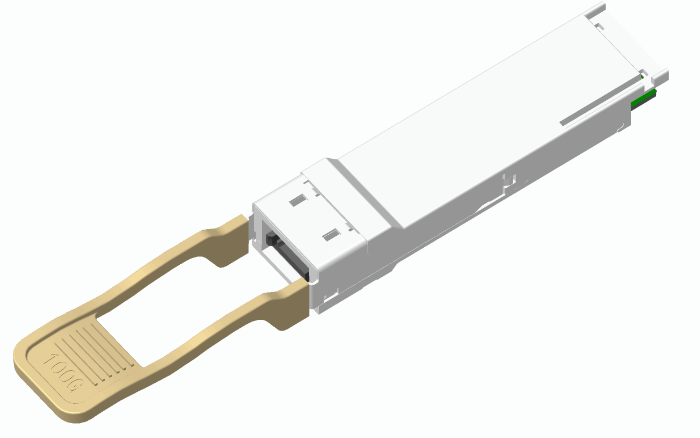
100G QSFP28 100m SR4 I-TEMP Transceivers
FEATURES
- Compliant with QSFP+ MSA Specification
- Wide Operating Temperature(-40°C~85°C)
- 4x25Gbps 850nm VCSEL-based Transmitter
- Maximum Link Length of 100m via OM4 Multimode Fiber(MMF)
APPLICATIONS
- Data Center Backbone
- 100GBASE-SR4 100G Ethernet
ABSOLUTE MAXIMUM RATINGS
| Parameter | Symbol | Conditions | Min. | Max. | Unit |
|---|---|---|---|---|---|
| Storage Temperature | TStorage | -40 | +85 | °C | |
| Relative Humidity | RH | 0 | +85 | % |
RECOMMENDED OPERATING CONDITIONS (Ta, unless noted)
| Parameter | Symbol | Conditions | Min. | Typ. | Max. | Unit |
|---|---|---|---|---|---|---|
| Case Temperature | TC | -40 | 85 | °C | ||
| Power Supply Voltage | VCC | 3.135 | 3.3 | 3.465 | V | |
| Signaling Rate each Channel | 25.78125 | Gbps | ||||
| Supply Noise Rejection | — | — | 100 | mV | ||
| Receiver Differential Data Output | — | 100 | Ohm | |||
| Operating Distance | D | @ OM3 MMF | — | — | 70 | m |
| Operating Distance | D | @ OM4 MMF | 100 | m |
ELECTRICAL CHARACTERISTICS (Ta, unless noted)
| Parameter | Symbol | Conditions | Min. | Typ. | Max. | Unit |
|---|---|---|---|---|---|---|
| Power Consumption | 3.5 | W | ||||
| Supply Current | Icc | 1050 | mA |
TRANSMITTER CHARACTERISTICS (T=25°C, unless noted)
| Parameter | Symbol | Conditions | Min. | Typ. | Max. | Unit |
|---|---|---|---|---|---|---|
| Signaling rate, each lane (range) | GBb | 25.78125 | GBb | |||
| Center Wavelength | λ | 840 | 850 | 860 | nm | |
| RMS Spectral Width | SW | 0.6 | nm | |||
| Average launch power, each lane | Pf | -8.4 | 2.4 | dBm | ||
| Optical Modulation Amplitude (OMA), each lane | TxOMA | -6.4 | 3 | dBm | ||
| Average launch power of OFF transmitter, each lane | -30 | dBm | ||||
| Extinction ratio | ER | 3 | dB | |||
| Optical return loss tolerance | 12 | dB |
RECEIVER CHARACTERISTICS (Ta, unless noted)
| Parameter | Symbol | Conditions | Min. | Typ. | Max. | Unit |
|---|---|---|---|---|---|---|
| Signaling rate, each lane (range) | GBb | 25.78125 | GBb | |||
| Center Wavelength | λ | 840 | 860 | nm | ||
| Damage threshold | 3.4 | dBm | ||||
| Average power at receiver input, each lane | -10.3 | 2.4 | dBm | |||
| Receive power, each lane (OMA) | 3 | dBm | ||||
| Receiver sensitivity (OMA) | SOMA | BER@5e-5 | -7.2 | dBm | ||
| Receiver reflectance | -12 | dB | ||||
| LOS Assert | LOSA | -30 | dBm | |||
| LOS De-Assert | LOSD | -10.5 | dBm | |||
| LOS Hysteresis | 0.5 | dB |
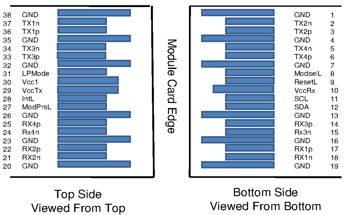
PIN ASSIGNMENT
PIN DESCRIPTION
| PIN | Logic | Symbol | Name/Description | Note |
|---|---|---|---|---|
| 1 | GND | Ground | ||
| 2 | CML-I | Tx2n | Transmitter Inverted Data Input | |
| 3 | CML-I | Tx2p | Transmitter Non-Inverted Data output | |
| 4 | GND | Ground | ||
| 5 | CML-I | Tx4n | Transmitter Inverted Data Input | |
| 6 | CML-I | Tx4p | Transmitter Non-Inverted Data output | |
| 7 | GND | Ground | ||
| 8 | LVTTL-I | ModSelL | Module Select | |
| 9 | LVTTL-I | ResetL | Module Reset | |
| 10 | VccRx | ﹢3.3V Power Supply Receiver | ||
| 11 | LVCMOS-I/O | SCL | 2-Wire Serial Interface Clock | |
| 12 | LVCMOS-I/O | SDA | 2-Wire Serial Interface Data | |
| 13 | GND | Ground | ||
| 14 | CML-O | Rx3p | Receiver Non-Inverted Data Output | |
| 15 | CML-O | Rx3n | Receiver Inverted Data Output | |
| 16 | GND | Ground | ||
| 17 | CML-O | Rx1p | Receiver Non-Inverted Data Output | |
| 18 | CML-O | Rx1n | Receiver Inverted Data Output | |
| 19 | GND | Ground | ||
| 20 | GND | Ground | ||
| 21 | CML-O | Rx2n | Receiver Inverted Data Output | |
| 22 | CML-O | Rx2p | Receiver Non-Inverted Data Output | |
| 23 | GND | Ground | ||
| 24 | CML-O | Rx4n | Receiver Inverted Data Output | |
| 25 | CML-O | Rx4p | Receiver Non-Inverted Data Output | |
| 26 | GND | Ground | ||
| 27 | LVTTL-O | ModPrsL | Module Present | |
| 28 | LVTTL-O | IntL | Interrupt | |
| 29 | VccTx | +3.3 V Power Supply transmitter | ||
| 30 | Vcc1 | +3.3 V Power Supply | ||
| 31 | LVTTL-I | LPMode | Low Power Mode | |
| 32 | GND | Ground | ||
| 33 | CML-I | Tx3p | Transmitter Non-Inverted Data Input | |
| 34 | CML-I | Tx3n | Transmitter Inverted Data Output | |
| 35 | GND | Ground | ||
| 36 | CML-I | Tx1p | Transmitter Non-Inverted Data Input | |
| 37 | CML-I | Tx1n | Transmitter Inverted Data Output | |
| 38 | GND | Ground |
Optical Interface Lanes and Assignment
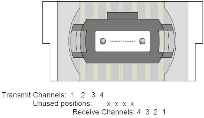
The optical interface port is a male MPO connector .The four fiber positions on the left as shown in the below Figure, with the key up, are used for the optical transmit signals (Channel 1 through 4). The fiber positions on the right are used for the optical receive signals (Channel 4 through 1). The central four fibers are physically present.
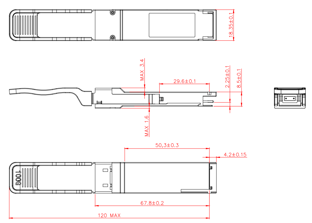
OUTLINE DIMENSIONS
Digital Diagnostic Monitor Accuracy
The following characteristics are defined over recommended operating conditions
| Parameter | Accuracy | Unit |
|---|---|---|
| Internally measured transceiver temperature | +/-3 | deg.C |
| Internally measured transceiver supply voltage | +/-3 | % |
| Measured Tx bias current | +/-10 | % |
| Measured Tx output power | +/-3 | dB |
| Measured Rx received average optical power | +/-3 | dB |
Order Information
| model number | product description |
|---|---|
| FTQ2-HG-SR4I | QSFP28, 100G, SR4 I-TEMP, -40℃~85℃ |
Company Information
| Company | 北亿纤通 | F-toneNetworks |
| Region | 中国四川天府新区 |
| Service Area | 全球 (Global) |
| Phone | 028-85255257 |
| Fax | 028-85977702 |
| Mobile | 19081343401 |
| Website | https://www.f-tone.com |
| HR Email | hr@f-tone.com |
| Sales Email | sales@f-tone.com |
| Technical Support | support@f-tone.com |
本产品为【100G QSFP28 SR4 Transceivers】产品线,详细信息,请联系我们的销售人员,谢谢!
Important Notice
Performance figures, data and any illustrative material provided in this data sheet are typical and must be specifically confirmed in writing by F-tone Networks before they become applicable to any particular order or contract. In accordance with the F-tone Networks policy of continuous improvement specifications may change without notice.
The publication of information in this data sheet does not imply freedom from patent or other protective rights of F-tone Networks or others. Further details are available from any F-tone Networks sales representative.