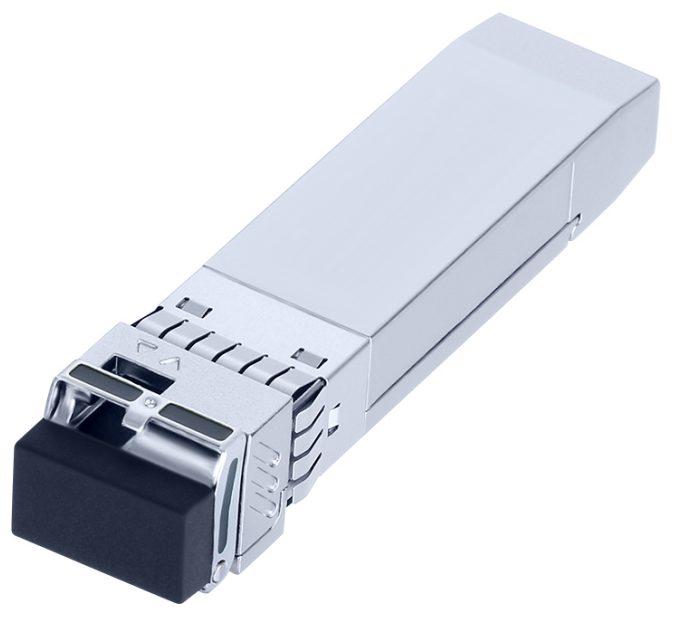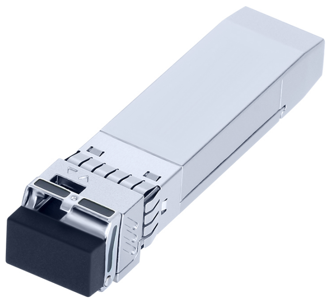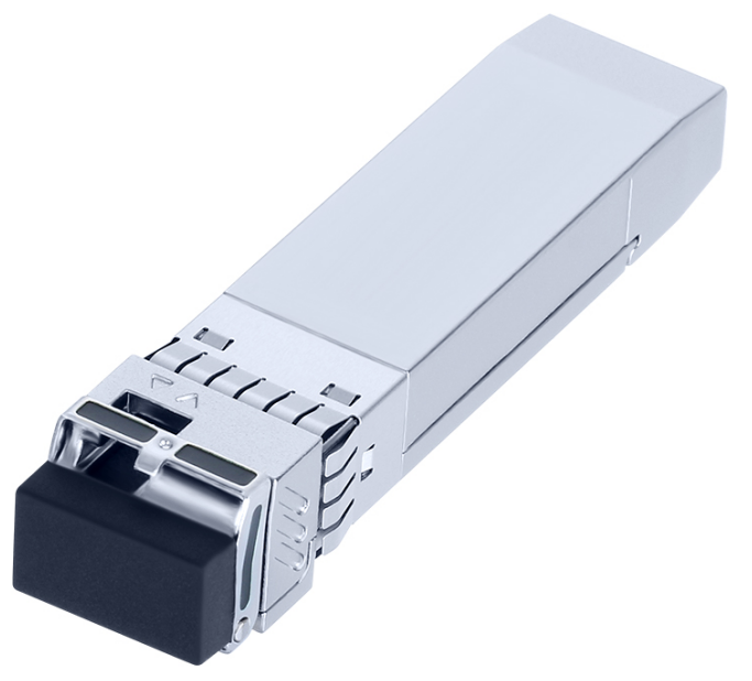

产品概述 / Description
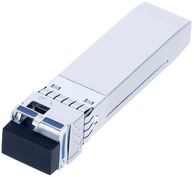
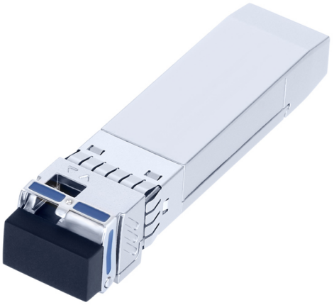
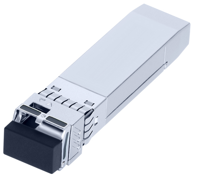
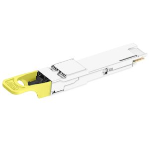
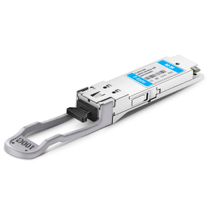
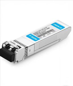
FTCS-Bxx25G-40D 系列是北亿纤通(F-tone Networks)25.78Gbps SFP28 单纤双向(BIDI)光模块,采用 DFB 激光器与 APD 雪崩光电探测器,单模光纤最远传输 40km,单 LC 接口,只需一根光纤即可完成双向传输,可节省一半光纤资源。系列包含 FTCS-B27A25G-40D(1270nm 发射 / 1310nm 接收)与 FTCS-B13A25G-40D(1310nm 发射 / 1270nm 接收)两个互补型号,需成对使用。
产品特点 / Product Features
- Up to 25.78Gbps Data Links
- Up to 40km transmission on SMF
- DFB Laser and APD receiver
- Metal enclosure, for lower EMI
- 2-wire interface with integrated Digital Diagnostic monitoring
- Hot-pluggable SFP28 footprint
- Compliant with SFP+ MSA and SFF-8472 with duplex LC receptacle
- Single 3.3V power supply
- Power dissipation < 1.5 W
- IEE Std 802.3-2022
- Operating case temperature:0 to +70°C
应用场景 / Applications
- 25GBASE-ER
- eCPRI and CPRI
Standard
- Compliant with SFF-8472 &8431
- RoHS Compliant.
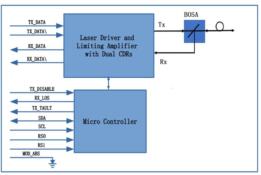
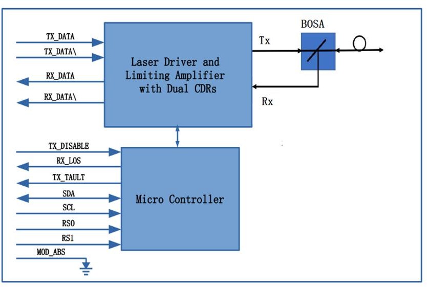
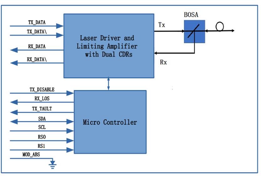
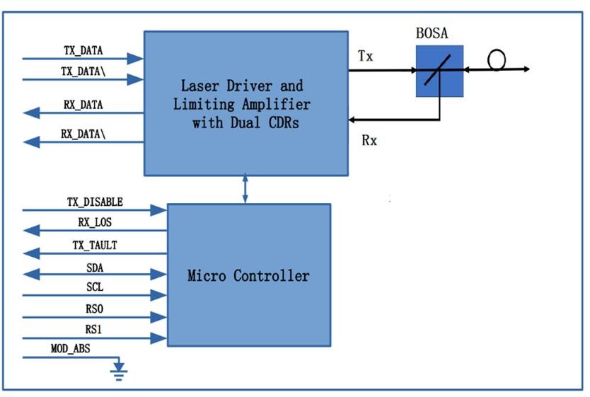
功能框图 / Transceiver Functional Diagram
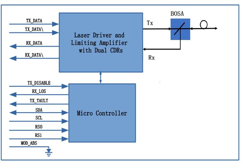
模块由发射、接收与控制三部分组成:发射侧由 MCU 通过 LD Bias / MOD-DEF 控制激光器驱动器(LD Driver),驱动 DFB 激光器输出光信号;接收侧由 PIN 光电探测器(内置跨阻放大器 TIA)与后级限幅放大器(Post Amp)恢复电信号;MCU 经 I2C(SDA/SCL)对外提供温度、电压、偏置电流、收发光功率等数字诊断信息,并处理 TX Disable、TX Fault、LOS 等控制与告警信号。
技术参数 / Specifications
绝对最大额定值 / Absolute Maximum Ratings
| Parameter | Symbol | Min | Max | Unit |
|---|---|---|---|---|
| Storage Temperature | Ts | -40 | 85 | ºC |
| Relative Humidity | RH | 5 | 95 | % |
| Power Supply Voltage | VCC | -0.3 | 4 | V |
| Signal Input Voltage | VSI | Vcc-0.3 | Vcc+0.3 | V |
| Rx Damage Threshold | PRdmg | -3 | dBm |
推荐工作条件 / Recommended Operating Conditions
| Parameter | Symbol | Min | Typical | Max | Unit |
|---|---|---|---|---|---|
| Case Operating Temperature | Tcase | 0 | 70 | ºC | |
| Power Supply Voltage | VCC | 3.14 | 3.3 | 3.47 | V |
| Power Supply Current | ICC | 420 | mA | ||
| Data Rate | BR | 25.78 | Gbps | ||
| Transmission Distance | TD | 40 | km | ||
| Coupled fiber | Single mode fiber | ||||
光学与电特性 / Optical and Electrical Characteristics
| Parameter | Symbol | Min | Typical | Max | Unit | Notes | ||
|---|---|---|---|---|---|---|---|---|
| Transmitter | ||||||||
| Centre Wavelength | λc | 1260 | 1280 | nm | ||||
| 1306 | 1322 | |||||||
| Spectral Width(-20dB) | Δλ | 1 | nm | |||||
| Average Output Power | Pout | -3 | 6 | dBm | 1 | |||
| Optical Modulation Amplitude (OMA) | 0 | 6 | dBm | 2 | ||||
| Average Launched Power(Laser Off) | Poff | -20 | dBm | |||||
| Launch power in OMA minus TDP (min) | -1 | dBm | ||||||
| Extinction Ratio | ER | 4 | dB | |||||
| Optical return loss tolerance | 20 | dB | ||||||
| Transmitter reflectance | -26 | dB | 3 | |||||
| Transmitter and dispersion penalty (TDP) | 2.7 | dB | ||||||
| Input differential impedance | Rin | 100 | Ω | |||||
| Single ended data input swing | Vin,pp | 180 | 700 | mV | ||||
| TX Disable | Disable | 2.0 | Vcc+0.3 | V | ||||
| Enable | 0 | 0.8 | V | |||||
| TX Fault | Fault | 2.0 | Vcc+0.3 | V | ||||
| Normal | 0 | 0.8 | V | |||||
| Output Eye Mask | {0.31,0.4,0.45,0.34,0.38,0.4} | |||||||
| Receiver | ||||||||
| Centre Wavelength | λc | 1306 | 1322 | nm | ||||
| 1260 | 1280 | |||||||
| Damage threshold | -3 | dBm | 4 | |||||
| Average receive power | -21 | -4 | dBm | 5 | ||||
| Receiver Sensitivity(OMA) | -19 | dBm | 6 | |||||
| Stressed receiver sensitivity (OMA) | -16.5 | dBm | 7 | |||||
| Receiver reflectance | -26 | dB | ||||||
| Los Of Signal Assert | PA | -35 | dBm | |||||
| Los Of Signal De-assert | PD | -19 | dBm | |||||
| LOS -Hysteresis | PHys | 0.5 | 5 | dB | ||||
| Differential data output swing | Vout,pp | 300 | 850 | mV | ||||
| LOS | High | 2.0 | Vcc+0.3 | V | ||||
| Low | 0.8 | V | ||||||
Notes:
Average launch power (min) is not the principal indicator of signal strength. A transmitter with launch power below this value cannot be compliant; however, a value above this does not ensure compliance.
The OMA (min) requirement holds even if the TDP < 1 dB.
Transmitter reflectance is defined looking into the transmitter.
The receiver shall be able to tolerate, without damage, continuous exposure to an optical input signal having this average power level。
Average receive power (min) is not the principal indicator of signal strength. A received power below this value cannot be compliant; however, a value above this does not ensure compliance。
Receiver sensitivity (OMA), (max) is optional.
Measured with conformance test signal at TP3 (see 159.7) for the BER specified in 159.1.1.
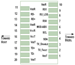
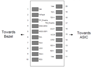
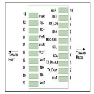
引脚定义 / Pin Descriptions
| Pin | Symbol | Name/Description | Notes |
|---|---|---|---|
| 1 | VEET | Transmitter Ground (Common with Receiver Ground) | 1 |
| 2 | TFAULT | Transmitter Fault. | 2 |
| 3 | TDIS | Transmitter Disable. Laser output disabled on high or open. | 3 |
| 4 | SDA | 2-wire Serial Interface Data Line | 4 |
| 5 | SCL | 2-wire Serial Interface Clock Line | 4 |
| 6 | MOD_ABS | Module Absent. Grounded within the module | 4 |
| 7 | RS0 | Rate Select 0, internal pull down | 5 |
| 8 | LOS | Loss of Signal indication. Logic 0 indicates normal operation. | 6 |
| 9 | RS1 | Rate Select 1, internal pull down | 5 |
| 10 | VEER | Receiver Ground (Common with Transmitter Ground) | 1 |
| 11 | VEER | Receiver Ground (Common with Transmitter Ground) | 1 |
| 12 | RD- | Receiver Inverted DATA out. AC Coupled | |
| 13 | RD+ | Receiver Non-inverted DATA out. AC Coupled | |
| 14 | VEER | Receiver Ground (Common with Transmitter Ground) | 1 |
| 15 | VCCR | Receiver Power Supply | |
| 16 | VCCT | Transmitter Power Supply | |
| 17 | VEET | Transmitter Ground (Common with Receiver Ground) | 1 |
| 18 | TD+ | Transmitter Non-Inverted DATA in. AC Coupled. | |
| 19 | TD- | Transmitter Inverted DATA in. AC Coupled. | |
| 20 | VEET | Transmitter Ground (Common with Receiver Ground) | 1 |
Notes:
Circuit ground is internally isolated from chassis ground.
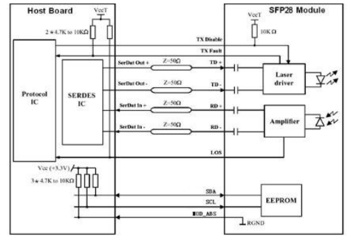
TFAULT is an open collector/drain output, which should be pulled up with a 4.7k – 10k Ohms resistor on the host board if intended for use. Pull up voltage should be between 2.0V to Vcc + 0.3V.A high output indicates a transmitter fault caused by either the TX bias current or the TX output power exceeding the preset alarm thresholds. A low output indicates normal operation. In the low state, the output is pulled to <0.8V.
Laser output disabled on TDIS>2.0V or open, enabled on TDIS<0.8V.
Should be pulled up with 4.7kΩ- 10kΩ host board to a voltage between 2.0V and 3.6V. MOD_ABS pulls line low to indicate module is plugged in.
Rate select can also be set through the 2-wire bus in accordance with SFF-8472. Rx Rate Select is set at Bit 3, Byte 110, Address A2h. Tx Rate Select is set at Bit 3, Byte 118, Address A2h.
LOS is open collector output. It should be pulled up with 4.7kΩ – 10kΩ on host board to a voltage between 2.0V and 3.6V. Logic 0 indicates normal operation; logic 1 indicates loss of signal.
推荐接口电路 / Recommended Interface Circuit
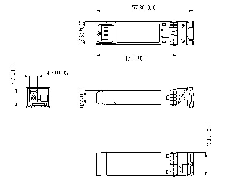
机械尺寸 / Mechanical Dimensions
订购信息 / Ordering Information
| Part Number | Product Description |
|---|---|
| FTCS-B27A25G-40D | 1270T/1310R, 25.78Gbps, LC, 40km, 0°C~+70°C, with DDM |
| FTCS-B13A25G-40D | 1310T/1270R, 25.78Gbps, LC, 40km, 0°C~+70°C, with DDM |
Important Notice
Performance figures, data and any illustrative material provided in this data sheet are typical and must be specifically confirmed in writing by F-tone Networks before they become applicable to any particular order or contract. In accordance with the F-tone Networks policy of continuous improvement specifications may change without notice.
The publication of information in this data sheet does not imply freedom from patent or other protective rights of F-tone Networks or others. Further details are available from any F-tone Networks sales representative.
地区:中国四川天府新区
服务区域:全球
联系方式:
企业电话:028-85255257 | 企业传真:028-85977702 | 企业手机:19081343401
Site:https://www.f-tone.com
人事部:hr@f-tone.com | 市场部:sales@f-tone.com | 技术支持:support@f-tone.com
本产品为光模块产品线,详细信息,请联系我们的销售人员,谢谢!
Important Notice
Performance figures, data and any illustrative material provided in this data sheet are typical and must be specifically confirmed in writing by F-tone Networks before they become applicable to any particular order or contract. In accordance with the F-tone Networks policy of continuous improvement specifications may change without notice. The publication of information in this data sheet does not imply freedom from patent or other protective rights of F-tone Networks or others. Further details are available from any F-tone Networks sales representative.