
产品特点 / Product Features
- Supports up to 25.78Gbps bit rates
- Hot-pluggable SFP+ footprint
- 50GHz ITU, C-Band & H-Band DWDM Cooled EML laser and APD photodiode,
- Up to 15km for SMF transmission
- Compliant with SFP+ MSA and SFF-8472 with duplex LC receptacle
- Compatible with RoHS
- Single +3.3V power supply
- Power dissipation <2.4W
- Real Time Digital Diagnostic Monitoring
- Operating case temperature:-40 to +85°C
应用场景 / Applications
- 25G Ethernet
- CPRI 10
产品概述 / Description
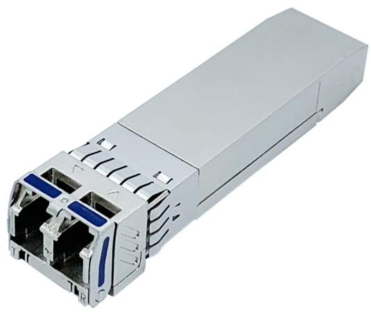
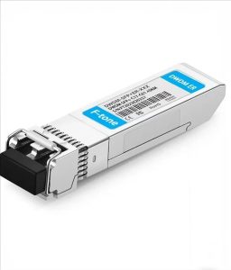
FTCS-Dxx25G-15DI 是北亿纤通(F-tone Networks)25G SFP28 DWDM 工业级光模块,采用 50GHz 通道间隔,覆盖 ITU-T C 波段 17~61 通道(191.7~196.1THz)与 H 波段通道,发射端为集成电吸收调制器与半导体制冷器(TEC)的 EML 激光器,接收端为 APD 雪崩光电探测器,在单模光纤上最远传输 15km,工作温度 -40~+85℃。模块符合 SFP28 MSA 与 SFF-8472,支持数字诊断监控,适合 5G 前传、城域汇聚等波分复用链路。
The SFP28 transceivers are high performance, cost effective modules supporting data rate of 25.78Gbps and 15km transmission distance with SMF.
The transceiver consists of three sections: a Cooled EML laser transmitter, a APD photodiode integrated with a trans-impedance preamplifier (TIA) and MCU control unit. All modules satisfy class I laser safety requirements.
The transceivers are compatible with SFP Multi-Source Agreement and SFF-8472 digital diagnostics functions.
功能框图 / Transceiver Functional Diagram
模块由发射、接收与控制三部分组成:发射侧由 MCU 通过 LD Bias / MOD-DEF 控制激光器驱动器(LD Driver),驱动 DFB 激光器输出光信号;接收侧由 PIN 光电探测器(内置跨阻放大器 TIA)与后级限幅放大器(Post Amp)恢复电信号;MCU 经 I2C(SDA/SCL)对外提供温度、电压、偏置电流、收发光功率等数字诊断信息,并处理 TX Disable、TX Fault、LOS 等控制与告警信号。
技术参数 / Specifications
绝对最大额定值 / Absolute Maximum Ratings
| Parameter | Symbol | Min | Max | Unit |
|---|---|---|---|---|
| Supply Voltage | Vcc | -0.5 | 4.5 | V |
| Storage Temperature | Ts | -40 | +85 | °C |
| Operating Humidity | – | 5 | 85 | % |
推荐工作条件 / Recommended Operating Conditions
| Parameter | Symbol | Min | Typical | Max | Unit |
|---|---|---|---|---|---|
| Operating Case Temperature | Tc | -40 | +85 | °C | |
| Power Supply Voltage | Vcc | 3.135 | 3.30 | 3.465 | V |
| Power Supply Current | Icc | 700 | mA | ||
| Data Rate | 25.78 | Gbps |
电特性 / Electrical Characteristics
| Parameter | Symbol | Min. | Typ. | Max. | Unit | Note |
|---|---|---|---|---|---|---|
| Transmitter | ||||||
| Data Input Swing Differential | VIN | 190 | 700 | mV | – | |
| Differential line input Impedance | RIN | 80 | 100 | 120 | Ohm | – |
| Transmitter Fault Output-High | VFaultH | 2 | – | Vcc | V | – |
| Transmitter Fault Output-Low | VFaultL | VEE | – | VEE +0.8 | V | – |
| Transmitter Disable Voltage- High | VDisH | 2 | – | Vcc | V | – |
| Transmitter Disable Voltage- low | VDisL | VEE | – | VEE +0.8 | V | – |
| Receiver | ||||||
| Differential line Output Impedance | ROUT | 80 | 100 | 120 | Ohm | – |
| Differential Data Output Voltage | VDR | 350 | – | 850 | mVp-p | – |
| LOS Output Voltage-High | VLOSH | 2 | – | Vcc | V | – |
| LOS Output Voltage-Low | VLOSL | VEE | – | VEE +0.8 | V | – |
| Others | ||||||
| Cold-Start time | Tstart-cooled | – | – | 35 | s | – |
光学与电特性 / Optical and Electrical Characteristics
| Parameter | Symbol | Min | Typical | Max | Unit | Notes | ||
|---|---|---|---|---|---|---|---|---|
| Transmitter | ||||||||
| Centre Wavelength | λc | 1528.77 | 1563.05 | nm | ||||
| Spectral Width(-20dB) | Δλ | 1 | nm | |||||
| Wavelength Drift | λ.max – λ.min | – | – | 0.03 | nm | |||
| Side-Mode Suppression Ratio | SMSR | 30 | – | dB | ||||
| Average Output Power | Pout | 0 | +5 | dBm | 1 | |||
| Extinction Ratio | ER | 6 | dB | |||||
| Data Input Swing Differential | VIN | 180 | 850 | mV | 2 | |||
| Input Differential Impedance | ZIN | 90 | 100 | 110 | Ω | |||
| TX Disable | Disable | 2.0 | Vcc | V | ||||
| Enable | 0 | 0.8 | V | |||||
| TX Fault | Fault | 2.0 | Vcc | V | ||||
| Normal | 0 | 0.8 | V | |||||
| Receiver | ||||||||
| Centre Wavelength | λc | 1260 | 1620 | nm | ||||
| Receiver Sensitivity | Psen EOL | -19 | dBm | 3,4 | ||||
| Avg. Receiver Sensitivity(EOL) @after 15km fiber transmission |
-16 | dBm | 3,4 | |||||
| Avg. Receiver Sensitivity(EOL) @after 10km fiber transmission |
-18 | dBm | 3,4 | |||||
| Receiver Overload | -6 | dBm | 3 | |||||
| LOS De-Assert | LOSD | -24 | dBm | |||||
| LOS Assert | LOSA | -35 | dBm | |||||
| LOS Hysteresis | 0.5 | dB | ||||||
| Data Output Swing Differential | Vout | 300 | 900 | mV | 5 | |||
| LOS | High | 2.0 | Vcc | V | ||||
| Low | 0.8 | V | ||||||
Notes:
1. The optical power is launched into SMF.
2. PECL input, internally AC-coupled and terminated.
3. Measured with a PRBS of 231-1 at 1 x 10-12 BER and ER>6 dB extinction ratio@10.3Gbps
4.Measured with a PRBS of 231-1 at 5 x 10⁻⁵ BER and ER>6 dB extinction ratio@25.78Gbps
5. Internally AC-coupled.
时序与电特性 / Timing and Electrical
| Parameter | Symbol | Min | Typical | Max | Unit |
|---|---|---|---|---|---|
| Tx Disable Negate Time | t_on | 1 | ms | ||
| Tx Disable Assert Time | t_off | 10 | µs | ||
| Time To Initialize, including Reset of Tx Fault | t_init | 300 | ms | ||
| Tx Fault Assert Time | t_fault | 100 | µs | ||
| Tx Disable To Reset | t_reset | 10 | µs | ||
| LOS Assert Time | t_loss_on | 100 | µs | ||
| LOS De-assert Time | t_loss_off | 100 | µs | ||
| Serial ID Clock Rate | f_serial_clock | 100 | 400 | KHz | |
| MOD_DEF (0:2)-High | VH | 2 | Vcc | V | |
| MOD_DEF (0:2)-Low | VL | 0.8 | V |
数字诊断 / Diagnostics
| Parameter | Range | Unit | Accuracy | Calibration |
|---|---|---|---|---|
| Temperature | -40 to +85 | °C | ±3°C | Internal |
| Voltage | 3.0 to 3.6 | V | ±3% | Internal |
| Bias Current | 0 to 120 | mA | ±10% | Internal |
| TX Power | 0 to +5 | dBm | ±3dB | Internal |
| RX Power | -19 to -6 | dBm | ±3dB | Internal |
数字诊断存储映射 / Digital Diagnostic Memory Map
The transceivers provide serial ID memory contents and diagnostic information about the present operating conditions by the 2-wire serial interface (SCL, SDA).
The diagnostic information with internal calibration or external calibration all are implemented, including received power monitoring, transmitted power monitoring, bias current monitoring, supply voltage monitoring and temperature monitoring.
The digital diagnostic memory map specific data field defines as following.
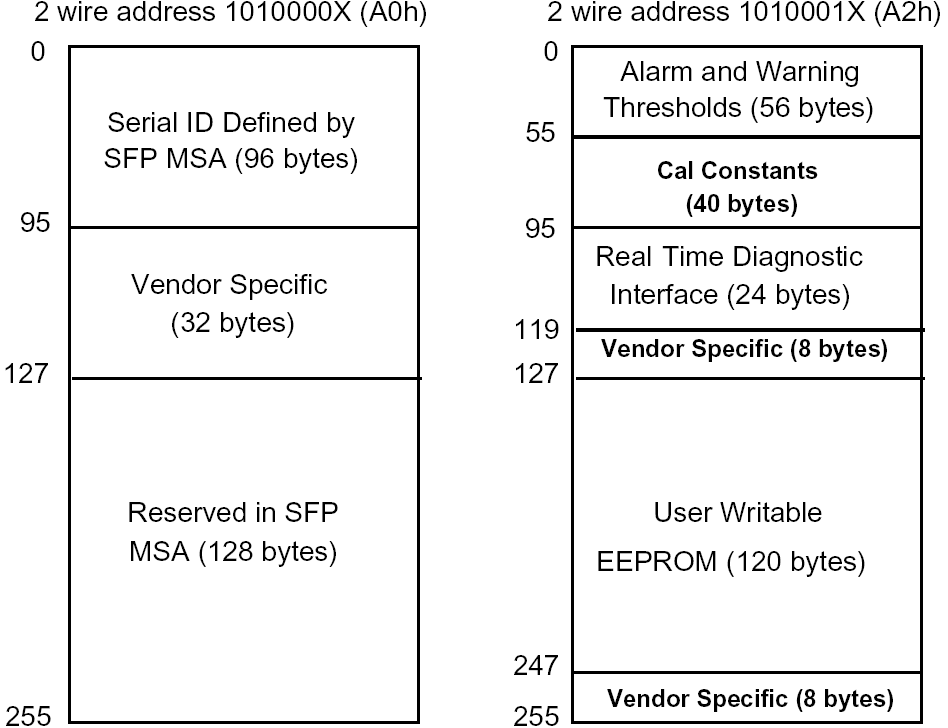
数字诊断监控与串行 ID 操作 / Digital Diagnostic Monitoring and Serial ID Operation
Serial ID and Map : A0h
| Address | HEX | Name of Fields | Description |
|---|---|---|---|
| 0 | 03 | Identifier | SFP/SFP+/SFP28 |
| 1 | 04 | Ext. Identifier | GBIC/SFF function is defined by serial ID only |
| 2 | 07 | Connector | LC |
| 3 | 00 | Infiniband Compliance | Not Specified |
| 4 | 00 | Reach Specifier | Not Specified |
| 5 | 00 | SONET | Not Specified |
| 6 | 00 | Ethernet Compliance | Not Specified |
| 7 | 00 | Fiber Channel link length | Not Specified |
| 8 | 00 | Transmitter technology | Unallocated |
| 9 | 00 | Transmission media | Not Specified |
| 10 | 00 | Fiber Channel Speed | Not Specified |
| 11 | 03 | Encoding | NRZ |
| 12 | FF | Nominal Bit Rate | >25.5 Gbps |
| 13 | 00 | Not Specified | |
| 14 | 0F | Length(9u)[km] | 15 Km |
| 15 | 96 | Length(9u)[m] | |
| 16 | 00 | Length(50u,OM2)[m] | Not support |
| 17 | 00 | Length(62.5u,OM1)[m] | Not support |
| 18 | 00 | Length(copper) | Not support |
| 19 | 00 | Length(50u,OM3)[m] | Not support |
| 20 | 43 | Vendor Name | |
| 21 | 68 | ||
| 22 | 65 | ||
| 23 | 6D | ||
| 24 | 4F | ||
| 25 | 70 | ||
| 26 | 74 | ||
| 27 | 69 | ||
| 28 | 63 | ||
| 29 | 73 | ||
| 30 | 20 | ||
| 31 | 20 | ||
| 32-35 | 20 | ||
| 33 | 20 | ||
| 34 | 20 | ||
| 35 | 20 | ||
| 36 | 03 | Extended Compliance Codes | |
| 37 | 6C | Vendor OUI | 6C-9B-C0 |
| 38 | 9B | ||
| 39 | C0 | ||
| 40 | 58 | Vendor PN | X |
| 41 | 50 | P | |
| 42 | 32 | 2 | |
| 43 | 38 | 8 | |
| 44 | 2D | – | |
| 45 | 44 | D | |
| 46 | 48 | H | |
| 47 | xx | x | |
| 48 | xx | x | |
| 49 | 47 | G | |
| 50 | 32 | 2 | |
| 51 | 35 | 5 | |
| 52 | 2D | – | |
| 53 | 31 | 1 | |
| 54 | 35 | 5 | |
| 55 | 46 | F | |
| 56 | 56 | Vendor Rev. | V |
| 57 | 31 | ||
| 58 | 2E | ||
| 59 | 30 | ||
| 60 | Wavelength[nm] | 1528.77-1563.05nm | |
| 61 | |||
| 62 | |||
| 63 | Varies | CC_BASE | Checksum over 0 to 62 |
| 64 | 2E | Option Values Cooled Transceiver[2] Power Level [1] Linear Receiver Output[0] | Retimer or CDR indicator.Power level 3 Cooled Transceiver Limit Receiver Output |
| 65 | 1A | Option Values Rate Select[5] Tx Disable[4] TX Fault[3] SD[2] LOS[1] | Tx Disable[4] TX Fault[3] LOS[1] |
| 66 | 67 | Bit Rate, max[%] | 103*0.25=25.75 Gbps |
| 67 | 00 | Bit Rate, min[%] | Not Specified |
| 68-83 | Varies | Vendor S/N | Varies |
| 84-91 | Varies | Date Code | Varies |
| 92 | 68 | Diagnostic Monitoring Type Digital diagnostic[6] Internally Cailbrated[5] Externally Calibrated[4] Average Power[3] Address change req[2] | Digital diagnostic[6] Internally Calibrated[5] Average Power[3] |
| 93 | F8 | Enhanced Options Alarm/Warm Impl.[7] Soft TX Dis Control[6] Soft TX Fault monitor[5] Soft Rx LOS monitor[4] Soft RATE_SELControl[3] App Select Control[2] Rate Select Control[1] | Alarm/Warm Impl.[7] Soft TX Dis Control[6] Soft TX Fault monitor[5] Soft Rx LOS monitor[4] Soft RATE_SEL Control[3] |
| 94 | 08 | SFF-8472 Compliance | Rev12.3 of SFF-8472 |
| 95 | Varies | CC_EXT | Check Sum Byte for Bytes 64 to 94 |
| 96-127 | Varies | Vendor specific | |
| 128-163 | 00 | Reserved | |
| 164-247 | 00 | Reserved | |
| 248-255 | 00 | Reserved |
Digital diagnostic monitoring : A2h
| Data Address | Size | Name of Field | Default Values | Data Address | Size | Name of Field | Default Values | ||
|---|---|---|---|---|---|---|---|---|---|
| Alarm and Warning Thresholds | Hex. | Dec. | unit | External Calibration Option | |||||
| 0 – 1 | 2 | Temp. High Alarm | 5F-00 | 95 | ℃ | 56 – 59 | 4 | RX_PWR(4) | 00-00-00-00h |
| 2 – 3 | 2 | Temp. Low Alarm | CE-00 | -50 | ℃ | 60 – 63 | 4 | RX_PWR(3) | 00-00-00-00h |
| 4 – 5 | 2 | Temp. High Warning | 5A-00 | 90 | ℃ | 64 – 67 | 4 | RX_PWR(2) | 00-00-00-00h |
| 6 – 7 | 2 | Temp. Low Warning | D3-00 | -45 | ℃ | 68 – 71 | 4 | RX_PWR(1) | 3F-80-00-00h |
| 8 – 9 | 2 | Voltage High Alarm | 8D-CC | 3.63 | V | 72 – 75 | 4 | RX_PWR(0) | 00-00-00-00h |
| 10 – 11 | 2 | Voltage Low Alarm | 74-04 | 2.97 | V | 76 – 77 | 2 | TX_I(Slope) | 01-00h |
| 12 – 13 | 2 | Voltage High Warning | 87-5A | 3.465 | V | 78 – 79 | 2 | TX_I(Offset) | 00-00h |
| 14 – 15 | 2 | Voltage Low Warning | 7A-76 | 3.135 | V | 80 – 81 | 2 | TX_PWR(Slope) | 01-00h |
| 16 – 17 | 2 | Bias High Alarm | FD-E8 | 130 | mA | 82 – 83 | 2 | TX_PWR(Offset) | 00-00h |
| 18 – 19 | 2 | Bias Low Alarm | 09-C4 | 5 | mA | 84 – 85 | 2 | T(Slope) | 01-00h |
| 20 – 21 | 2 | Bias High Warning | EA-60 | 120 | mA | 86 – 87 | 2 | T(Offset) | 00-00h |
| 22 – 23 | 2 | Bias Low Warning | 13-88 | 10 | mA | 88 – 89 | 2 | V(Slope) | 01-00h |
| 24 – 25 | 2 | TX Power High Alarm | AE-7C | 6.5 | dBm | 90 – 91 | 2 | V(Offset) | 00-00h |
| 26 – 27 | 2 | TX Power Low Alarm | 1F-07 | -1.0 | dBm | 92 – 94 | 3 | Reserved | – |
| 28 – 29 | 2 | TX Power High Warning | 8A-99 | 5.5 | dBm | 95 | 1 | Checksum(address 0 to 94) | – (Note 3) |
| 30 – 31 | 2 | TX Power Low Warning | 27-10 | 0.0 | dBm | A/D Values and Status Bits(Ref. page 17) | |||
| 32 – 33 | 2 | RX Power High Alarm | 13-94 | -3.0 | dBm | 96 – 97 | 2 | Measured Module Temp. | Variable |
| 34 – 35 | 2 | RX Power Low Alarm | 00-32 | -23.0 | dBm | 98 – 99 | 2 | Measured Supply Voltage | Variable |
| 36 – 37 | 2 | RX Power High Warning | 0C-5A | -5.0 | dBm | 100 – 101 | 2 | Measured TX Bias Current | Variable |
| 38 – 39 | 2 | RX Power Low Warning | 00-4F | -21.0 | dBm | 102 – 103 | 2 | Measured TX Output Power | Variable |
| 40 – 41 | 2 | Laser T/ High Alarm | 41-00 | 65 | ℃ | 104 – 105 | 2 | Measured RX Input Power | Variable |
| 42 – 43 | 2 | Laser T/ Low Alarm | 14-00 | 20 | ℃ | 106 – 109 | 4 | Reserved | 00-00-00-00h |
| 44 – 45 | 2 | Laser T/ High Warning | 3C-00 | 60 | ℃ | Optional Status/Control Bits | |||
| 46 – 47 | 2 | Laser T/ Low Warning | 19-00 | 25 | ℃ | 110 | 1 | Optional Status and Control | Variable |
| 48 – 49 | 2 | TEC Current High Alarm | 2E-E0 | 1.2 | A | 111 | 1 | Reserved | 00h |
| 50 – 51 | 2 | TEC Current Low Alarm | D1-20 | -1.2 | A | 112 – 113 | 2 | Alarm Flag(set) | Variable (Not supported) |
| 52 – 53 | 2 | TEC Current High Warning | 27-10 | 1.0 | A | 114 | 1 | Tx input equalization | A0h |
| 54 – 55 | 2 | TEC Current Low Warning | D8-F0 | -1.0 | A | 115 | 1 | RX output emphasis | 50h |
| – | 116-117 | 2 | Warning Flag(set) | Variable | |||||
| – | 118 | 1 | Extended Control/Status | Variable | |||||
| – | 119 – 122 | 4 | Reserved | 00-00-00-00h | |||||
| – | 123 – 126 | 4 | Password Entry | 00-00-00-00h | |||||
| – | 127 | 1 | Table Select | 00h | |||||
| – | 128 – 247 | 120 | User EEPROM | 00h | |||||
| – | 248 – 255 | 8 | Vendor Specific | 00h | |||||
| Note 3: The check code shall be the low order 8 bits of the sum of the contents of all the bytes from byte 0 to byte 94 inclusive. | |||||||||
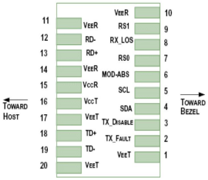
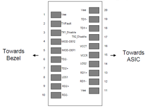
引脚定义 / Pin Descriptions
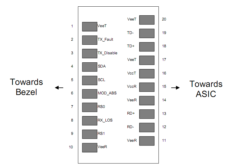
| Pin | Signal Name | Description | Plug Seq. | Notes |
|---|---|---|---|---|
| 1 | VEET | Transmitter Ground | 1 | |
| 2 | TX FAULT | Transmitter Fault Indication | 3 | Note 1 |
| 3 | TX DISABLE | Transmitter Disable | 3 | Note 2 |
| 4 | SDA | SDA Serial Data Signal | 3 | |
| 5 | SCL | SCL Serial Clock Signal | 3 | |
| 6 | MOD_ABS | Module Absent. Grounded within the module | 3 | |
| 7 | RS0 | Not Connected | 3 | |
| 8 | LOS | Loss of Signal | 3 | Note 3 |
| 9 | RS1 | Not Connected | 3 | |
| 10 | VEER | Receiver ground | 1 | |
| 11 | VEER | Receiver ground | 1 | |
| 12 | RD- | Inv. Received Data Out | 3 | Note 4 |
| 13 | RD+ | Received Data Out | 3 | Note 4 |
| 14 | VEER | Receiver ground | 1 | |
| 15 | VCCR | Receiver Power Supply | 2 | |
| 16 | VCCT | Transmitter Power Supply | 2 | |
| 17 | VEET | Transmitter Ground | 1 | |
| 18 | TD+ | Transmit Data In | 3 | Note 5 |
| 19 | TD- | Inv. Transmit Data In | 3 | Note 5 |
| 20 | VEET | Transmitter Ground | 1 |
Notes:
Plug Seq.: Pin engagement sequence during hot plugging.
1) TX Fault is an open collector output, which should be pulled up with a 4.7k~10kΩ resistor on the host board to a voltage between 2.0V and Vcc+0.3V. Logic 0 indicates normal operation; Logic 1 indicates a laser fault of some kind. In the low state, the output will be pulled to less than 0.8V.
2) Laser output disabled on TDIS >2.0V or open, enabled on TDIS <0.8V.
3) LOS is open collector output. Should be pulled up with 4.7k~10kΩ on host board to a voltage between 2.0V and 3.6V. Logic 0 indicates normal operation; logic 1 indicates loss of signal.
4) RD-/+: These are the differential receiver outputs. They are internally AC-coupled 100 differential lines which should be terminated with 100Ω (differential) at the user SERDES.
5) TD-/+: These are the differential transmitter inputs. They are internally AC-coupled, differential lines with 100Ω differential termination inside the module.
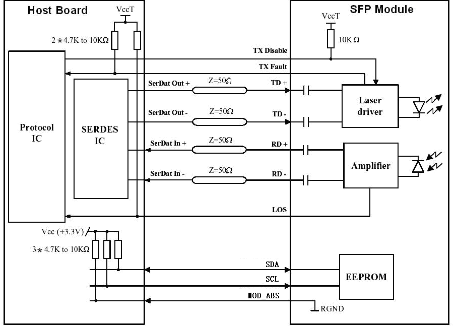
推荐接口电路 / Recommended Interface Circuit
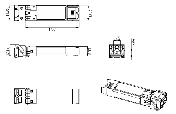
机械尺寸 / Mechanical Dimensions
订购信息 / Ordering Information
| Part Number | Product Description |
|---|---|
| FTCS-Dxx25G-15DI | 1528.77~1563.05nm C-Band DWDM,15km, DDM, -40°C~+85°C |
| FTCS-Dxx25G-15DI | 1528.38~1563.46nm H-Band DWDM 15km, DDM, -40°C~+85°C |
| λC Wavelength Guide(C-Band) | |||||
|---|---|---|---|---|---|
| ITU Channel Product Code |
Frequency(THz) | Wavelength | ITU Channel Product Code |
Frequency(THz) | Wavelength |
| 17 | 191.70 | 1563.86 | 40 | 194.00 | 1545.32 |
| 18 | 191.80 | 1563.05 | 41 | 194.10 | 1544.53 |
| 19 | 191.90 | 1562.23 | 42 | 194.20 | 1543.73 |
| 20 | 192.00 | 1561.42 | 43 | 194.30 | 1542.94 |
| 21 | 192.10 | 1560.61 | 44 | 194.40 | 1542.14 |
| 22 | 192.20 | 1559.79 | 45 | 194.50 | 1541.35 |
| 23 | 192.30 | 1558.98 | 46 | 194.60 | 1540.56 |
| 24 | 192.40 | 1558.17 | 47 | 194.70 | 1539.77 |
| 25 | 192.50 | 1557.36 | 48 | 194.80 | 1538.98 |
| 26 | 192.60 | 1556.55 | 49 | 194.90 | 1538.19 |
| 27 | 192.70 | 1555.75 | 50 | 195.00 | 1537.40 |
| 28 | 192.80 | 1554.94 | 51 | 195.10 | 1536.61 |
| 29 | 192.90 | 1554.13 | 52 | 195.20 | 1535.82 |
| 30 | 193.00 | 1553.33 | 53 | 195.30 | 1535.04 |
| 31 | 193.10 | 1552.52 | 54 | 195.40 | 1534.25 |
| 32 | 193.20 | 1551.72 | 55 | 195.50 | 1533.47 |
| 33 | 193.30 | 1550.92 | 56 | 195.60 | 1532.68 |
| 34 | 193.40 | 1550.12 | 57 | 195.70 | 1531.90 |
| 35 | 193.50 | 1549.32 | 58 | 195.80 | 1531.12 |
| 36 | 193.60 | 1548.51 | 59 | 195.90 | 1530.33 |
| 37 | 193.70 | 1547.72 | 60 | 196.00 | 1529.55 |
| 38 | 193.80 | 1546.92 | 61 | 196.10 | 1528.77 |
| 39 | 193.9 | 1546.12 | |||
| λC Wavelength Guide(H-Band) | |||||
| ITU Channel Product Code |
Frequency(THz) | Wavelength | ITU Channel Product Code |
Frequency(THz) | Wavelength |
| 17 | 191.75 | 1563.46 | 40 | 194.05 | 1544.92 |
| 18 | 197.85 | 1562.64 | 41 | 194.15 | 1544.13 |
| 19 | 191.95 | 1561.83 | 42 | 194.25 | 1543.33 |
| 20 | 192.05 | 1561.03 | 43 | 194.35 | 1542.54 |
| 21 | 192.15 | 1560.20 | 44 | 194.45 | 1541.75 |
| 22 | 192.25 | 1559.39 | 45 | 194.55 | 1540.95 |
| 23 | 192.35 | 1558.58 | 46 | 194.65 | 1540.16 |
| 24 | 192.45 | 1557.77 | 47 | 194.75 | 1539.37 |
| 25 | 192.55 | 1556.96 | 48 | 194.85 | 1538.58 |
| 26 | 192.65 | 1556.15 | 49 | 194.95 | 1537.79 |
| 27 | 192.75 | 1555.34 | 50 | 195.05 | 1537.00 |
| 28 | 192.85 | 1554.54 | 51 | 195.15 | 1536.22 |
| 29 | 192.95 | 1553.73 | 52 | 195.25 | 1535.43 |
| 30 | 193.05 | 1552.93 | 53 | 195.35 | 1534.64 |
| 31 | 193.15 | 1552.12 | 54 | 195.45 | 1533.86 |
| 32 | 193.25 | 1551.32 | 55 | 195.55 | 1533.07 |
| 33 | 193.35 | 1550.52 | 56 | 195.65 | 1532.29 |
| 34 | 193.45 | 1549.72 | 57 | 195.75 | 1531.51 |
| 35 | 193.55 | 1548.91 | 58 | 195.85 | 1530.72 |
| 36 | 193.65 | 1548.11 | 59 | 195.95 | 1529.94 |
| 37 | 193.75 | 1547.32 | 60 | 196.05 | 1529.16 |
| 38 | 193.85 | 1546.52 | 61 | 196.15 | 1528.38 |
| 39 | 193.95 | 1545.72 | – | – | – |
Important Notice
Performance figures, data and any illustrative material provided in this data sheet are typical and must be specifically confirmed in writing by F-tone Networks before they become applicable to any particular order or contract. In accordance with the F-tone Networks policy of continuous improvement specifications may change without notice.
The publication of information in this data sheet does not imply freedom from patent or other protective rights of F-tone Networks or others. Further details are available from any F-tone Networks sales representative.
地区:中国四川天府新区
服务区域:全球
联系方式:
企业电话:028-85255257 | 企业传真:028-85977702 | 企业手机:19081343401
Site:https://www.f-tone.com
人事部:hr@f-tone.com | 市场部:sales@f-tone.com | 技术支持:support@f-tone.com
本产品为光模块产品线,详细信息,请联系我们的销售人员,谢谢!
Important Notice
Performance figures, data and any illustrative material provided in this data sheet are typical and must be specifically confirmed in writing by F-tone Networks before they become applicable to any particular order or contract. In accordance with the F-tone Networks policy of continuous improvement specifications may change without notice. The publication of information in this data sheet does not imply freedom from patent or other protective rights of F-tone Networks or others. Further details are available from any F-tone Networks sales representative.