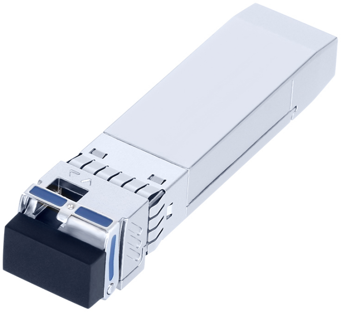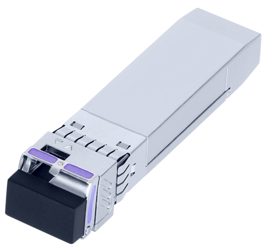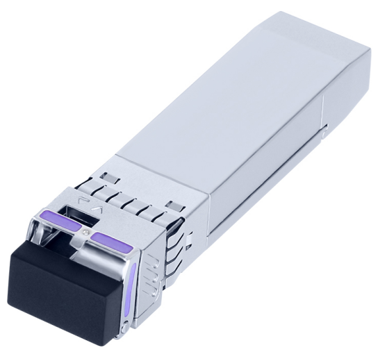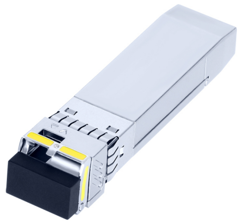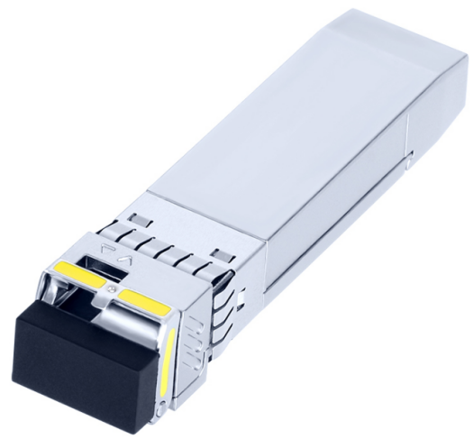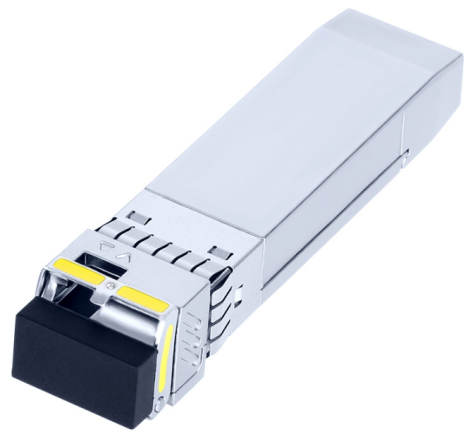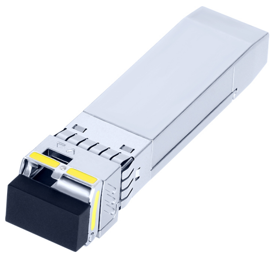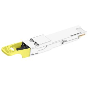
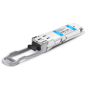

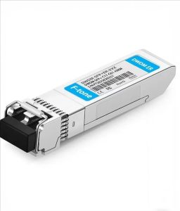
FTCS-851X-02D 是一款 10Gb/s 850nm 多模 SFP+ 光收发模块,在 OM3 多模光纤上传输距离可达 300 m,工作温度 0~+70℃(商业级)。模块采用 VCSEL 激光器与 PIN 接收器,功耗小于 1 W,金属外壳降低 EMI,双工 LC 接口,单 3.3V 供电,内置数字诊断监控,符合 SFP+ MSA、SFF-8431、SFF-8472 与 IEEE 802.3ae 10GBASE-SR,适用于 10G 以太网与数据中心短距互联。
产品特点 / Product Features
Up to 11.1Gbps Data Links
Up to 300m transmission on MMF
Power dissipation < 1W
VSCEL laser and PIN receiver
Metal enclosure, for lower EMI
2-wire interface with integrated Digital Diagnostic monitoring
Hot-pluggable SFP+ footprint
Specifications compliant with SFF 8472
Compliant with SFP+ MSA with LC connector
Single 3.3V power supply
Case operating temperature range:0°C to 70°C
应用场景 / Applications
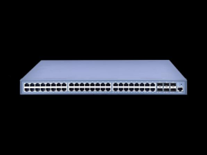
10GBASE-SR/SW & 10G Ethernet
标准符合性 / Standards
Compliant to SFP+ SFF-8431
Compliant to 802.3ae 10GBASE-SR.
RoHS Compliant.
技术参数 / Specifications
绝对最大额定值 / Absolute Maximum Ratings
| Parameter | Symbol | Min. | Typ. | Max. | Unit | Note |
|---|---|---|---|---|---|---|
| Storage Temperature | Ts | -40 | – | 85 | ºC | |
| Relative Humidity | RH | 5 | – | 95 | % | |
| Power Supply Voltage | VCC | -0.3 | – | 4 | V | |
| Signal Input Voltage | Vcc-0.3 | – | Vcc+0.3 | V |
推荐工作条件 / Recommended Operating Conditions
| Parameter | Symbol | Min. | Typ. | Max. | Unit | Note |
|---|---|---|---|---|---|---|
| Case Operating Temperature | Tcase | 0 | – | 70 | ºC | Without air flow |
| Power Supply Voltage | VCC | 3.14 | 3.3 | 3.47 | V | |
| Power Supply Current | ICC | – | 300 | mA | ||
| Data Rate | BR | 10.3125 | Gbps | |||
| Transmission Distance | TD | – | 300 | m | ||
| Coupled fiber | Multi mode fiber | 50/125um MMF | ||||
光学特性 / Optical Characteristics
| Parameter | Symbol | Min | Typ | Max | Unit | Note |
|---|---|---|---|---|---|---|
| Transmitter | ||||||
| Output Opt. Power | POUT | -6 | -1 | dBm | 1 | |
| Optical Wavelength | λ | 840 | 850 | 860 | nm | |
| Optical Extinction Ratio | ER | 3.5 | dB | |||
| RIN | RIN | -128 | Db/Hz | |||
| Output Eye Mask | Compliant with IEEE 802.3ae | |||||
| Receiver | ||||||
| Rx Sensitivity | RSENS | -11 | dBm | 2 | ||
| Input Saturation Power (Overload) | Psat | -1 | dBm | |||
| Wavelength Range | λC | 770 | 850 | 860 | nm | |
| LOS De -Assert | LOSD | -14 | dBm | |||
| LOS Assert | LOSA | -30 | dBm | |||
| LOS Hysteresis | 0.5 | dB | ||||
Notes:
Class 1 Laser Safety per FDA/CDRH and IEC-825-1 regulations.
Measured with a PRBS 231-1 test pattern, @10.325Gb/s, BER<10-12 .
电特性 / Electrical Characteristics
| Parameter | Symbol | Min | Typ | Max | Unit | Noet |
|---|---|---|---|---|---|---|
| Supply Voltage | Vcc | 3.14 | 3.3 | 3.46 | V | |
| Supply Current | Icc | 300 | mA | |||
| Transmitter | ||||||
| Input differential impedance | Rin | 100 | Ω | 1 | ||
| Single ended data input swing | Vin,pp | 180 | 700 | mV | ||
| Transmit Disable Voltage | VD | Vcc–1.3 | Vcc | V | ||
| Transmit Enable Voltage | VEN | Vee | Vee+ 0.8 | V | 2 | |
| Transmit Disable Assert Time | 10 | us | ||||
| Receiver | ||||||
| Differential data output swing | Vout,pp | 300 | 850 | mV | 3 | |
| Data output rise time | tr | 28 | ps | 4 | ||
| Data output fall time | tf | 28 | ps | 4 | ||
| LOS Fault | VLOS fault | Vcc–1.3 | VccHOST | V | 5 | |
| LOS Normal | VLOS norm | Vee | Vee+0.8 | V | 5 | |
| Power Supply Rejection | PSR | 100 | mVpp | 6 | ||
Notes:
1. Connected directly to TX data input pins. AC coupled thereafter.
2. Or open circuit.
3. Into 100 ohms differential termination.
4. These are unfiltered 20-80% values
5. Loss Of Signal is LVTTL. Logic 0 indicates normal operation; logic 1 indicates no signal detected.
6. Receiver sensitivity is compliant with power supply sinusoidal modulation of 20 Hz to 1.5 MHz up to specified value applied through the recommended power supply filtering network.
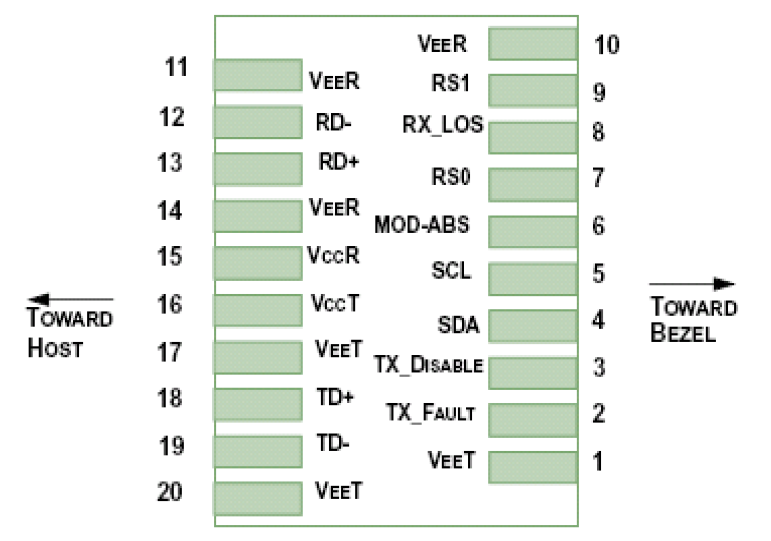
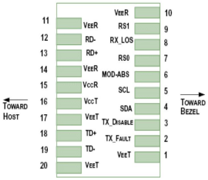
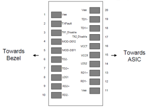
引脚定义 / Pin Assignment
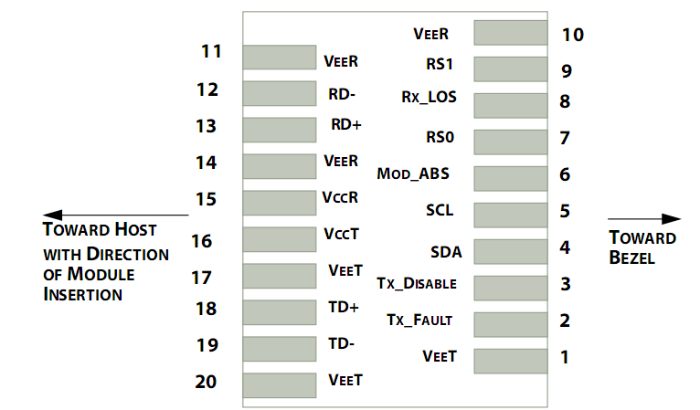
引脚定义表 / Pin Descriptions
| Pin | Symbol | Name/Description | NOTE |
|---|---|---|---|
| 1 | VEET | Transmitter Ground (Common with Receiver Ground) | 1 |
| 2 | TFAULT | Transmitter Fault. | 2 |
| 3 | TDIS | Transmitter Disable. Laser output disabled on high or open. | 3 |
| 4 | SDA | 2-wire Serial Interface Data Line | 4 |
| 5 | SCL | 2-wire Serial Interface Clock Line | 4 |
| 6 | MOD_ABS | Module Absent. Grounded within the module | 4 |
| 7 | RS0 | Rate Select 0 | 5 |
| 8 | LOS | Loss of Signal indication. Logic 0 indicates normal operation. | 6 |
| 9 | RS1 | No connection required | 1 |
| 10 | VEER | Receiver Ground (Common with Transmitter Ground) | 1 |
| 11 | VEER | Receiver Ground (Common with Transmitter Ground) | 1 |
| 12 | RD- | Receiver Inverted DATA out. AC Coupled | |
| 13 | RD+ | Receiver Non-inverted DATA out. AC Coupled | |
| 14 | VEER | Receiver Ground (Common with Transmitter Ground) | 1 |
| 15 | VCCR | Receiver Power Supply | |
| 16 | VCCT | Transmitter Power Supply | |
| 17 | VEET | Transmitter Ground (Common with Receiver Ground) | 1 |
| 18 | TD+ | Transmitter Non-Inverted DATA in. AC Coupled. | |
| 19 | TD- | Transmitter Inverted DATA in. AC Coupled. | |
| 20 | VEET | Transmitter Ground (Common with Receiver Ground) | 1 |
Notes:
1. Circuit ground is internally isolated from chassis ground.
2. TFAULT is an open collector/drain output, which should be pulled up with a 4.7k – 10k Ohms resistor on the host board if intended for use. Pull up voltage should be between 2.0V to Vcc + 0.3V.A high output indicates a transmitter fault caused by either the TX bias current or the TX output power exceeding the preset alarm threshold. A low output indicates normal operation. In the low state, the output is pulled to <0.8V.
3. Laser output disabled on TDIS >2.0V or open, enabled on TDIS <0.8V.
4. Should be pulled up with 4.7kΩ- 10kΩ host board to a voltage between 2.0V and 3.6V. MOD_ABS pulls line low to indicate module is plugged in.
5. Internally pulled down per SFF-8431 Rev 4.1.
6. LOS is open collector output. It should be pulled up with 4.7kΩ – 10kΩ on host board to a voltage between 2.0V and 3.6V. Logic 0 indicates normal operation; logic 1 indicates loss of signal.
数字诊断功能 / Digital Diagnostic Functions
F-tone Networks’s FTCS-851X-02D transceivers support the 2-wire serial communication protocol as defined in the SFP+ MSA. The standard SFP serial ID provides access to identification information that describes the transceiver’s capabilities, standard interfaces, manufacturer, and other information.
Additionally, F-tone Networks’s SFP+ transceivers provide a unique enhanced digital diagnostic monitoring interface, which allows real-time access to device operating parameters such as transceiver temperature, laser bias current, transmitted optical power, received optical power and transceiver supply voltage. It also defines a sophisticated system of alarm and warning flags, which alerts end-users when particular operating parameters are outside of a factory set normal range.
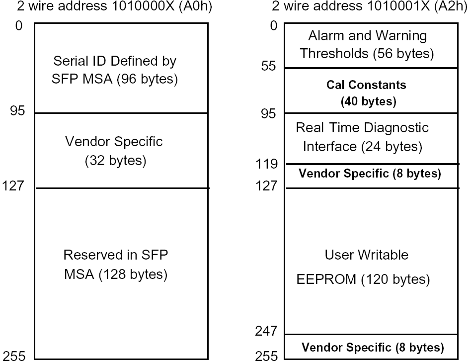
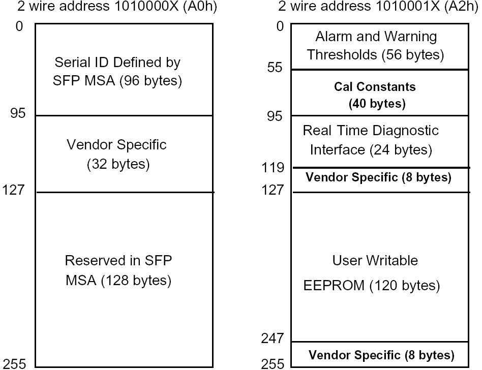
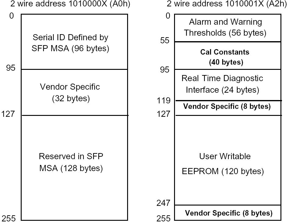
The SFP MSA defines a 256-byte memory map in EEPROM that is accessible over a 2-wire serial interface at the 8 bit address 1010000X (A0h).The digital diagnostic monitoring interface makes use of the 8 bit address 1010001X (A2h), so the originally defined serial ID memory map remains unchanged.
The operating and diagnostics information is monitored and reported by a Digital Diagnostics Transceiver Controller (DDTC) inside the transceiver, which is accessed through a 2-wire serial interface. When the serial protocol is activated, the serial clock signal (SCL, Mod Def 1) is generated by the host. The positive edge clocks data into the SFP transceiver into those segments of the E2PROM that are not write-protected. The negative edge clocks data from the SFP transceiver. The serial data signal (SDA, Mod Def 2) is bi-directional for serial data transfer. The host uses SDA in conjunction with SCL to mark the start and end of serial protocol activation. The memories are organized as a series of 8-bit data words that can be addressed individually or sequentially.
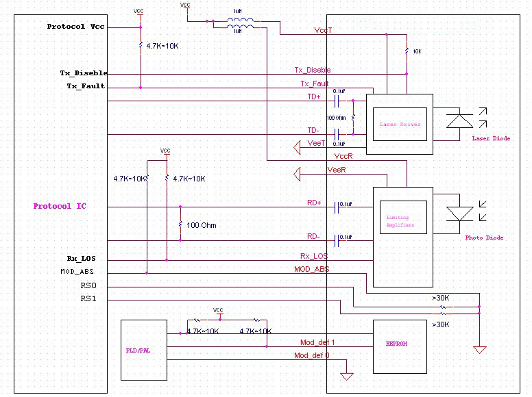
主机-模块接口框图 / Host – Transceiver Interface Block Diagram
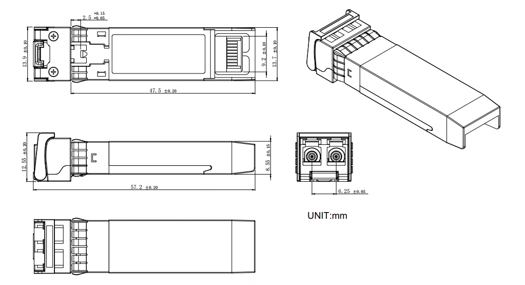
机械规格 / Mechanical Specifications
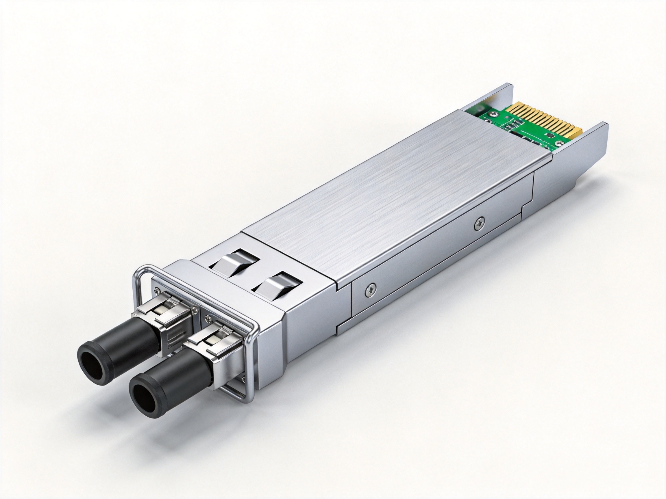
Comply to SFF-8432 rev. 5.0, the improved Pluggable form factor specification.
法规符合性 / Regulatory Compliance
| Feature | Reference | Performance |
|---|---|---|
| Electrostatic discharge(ESD) | IEC/EN 61000-4-2 | Compatible with standards |
| Electromagnetic Interference (EMI) | FCC Part 15 Class B EN 55022 Class B (CISPR 22A) | Compatible with standards |
| Laser Eye Safety | FDA 21CFR 1040.10, 1040.11 IEC/EN 60825-1,2 | Class 1 laser product |
| Component Recognition | IEC/EN 60950 ,UL | Compatible with standards |
| ROHS | 2002/95/EC | Compatible with standards |
| EMC | EN61000-3 | Compatible with standards |
订购信息 / Ordering Information
| Part Number | Product Description |
|---|---|
| FTCS-851X-02D | Multimode fiber dual fiber,10G,300m,850nm,LC interface |
本型号为商业级(0~+70℃)版本;工业级(-40~+85℃)同规格型号为 FTCS-851X-02DI。
地区:中国四川天府新区
服务区域:全球
联系方式:
企业电话:028-85255257 | 企业传真:028-85977702 | 企业手机:19081343401
Site:https://www.f-tone.com
人事部:hr@f-tone.com | 市场部:sales@f-tone.com | 技术支持:support@f-tone.com
本产品为10G SFP+光模块产品线,详细信息,请联系我们的销售人员,谢谢!
Important Notice
Performance figures, data and any illustrative material provided in this data sheet are typical and must be specifically confirmed in writing by F-tone Networks before they become applicable to any particular order or contract. In accordance with the F-tone Networks policy of continuous improvement specifications may change without notice. The publication of information in this data sheet does not imply freedom from patent or other protective rights of F-tone Networks or others. Further details are available from any F-tone Networks sales representative.