10/100/Hot Pluggable, 1.25Gb/s,Cat-5 UTP Cable, 100m
1000BASE-T SFP Copper Transceiver
FTCS-13RG-xxI
Features:
- Up to 1.25Gb/s bi-directional data links
- Hot-pluggable SFP footprint
- Extended case temperature range (-40°C to +85°C )
- Fully metallic enclosure for low EMI
- Low power dissipation
- Compact RJ-45 connector assembly
- Detailed product information in EEPROM
- +3.3V single power supply
- Access to physical layer IC via 2-wire serial bus
- 10/100/1000 BASE-T operation in host systems with SGMII interface
- Compliant with SFP MSA
- Compliant with IEEE Std 802.3
- Compliant with FCC 47 CFR Part 15, Class B
- RoHS Compliant Products
Applications:
- 1.25 Gigabit Ethernet over Cat 5 cable
- Switch/Router to Switch/Router Link
- High speed I/O for file severs
Description:
F-tone Networks’s 10/100/1000BASE-T Copper Small Form Pluggable (SFP) transceivers are based on the SFP Multi Source Agreement (MSA). Theyare compatible with the Gigabit Ethernet and 1000BASE-T standards as specified in IEEE Std 802.3. They are RoHS compliant and per Directive 2011/65/EU. The 1000BASE-T physical layer IC (PHY) can be accessed via I2C, allowing access to all PHY settings and features.They support 10/100/1000 BASE-T operation in host systems with SGMII interface and auto-negotiation. FTCS-13RG-xxI-L shall support Rx_LOS as link indication function, and FTCS-13RG-xxI shall not support Rx_LOS as link indication feature (RX_LOS is internally grounded).
SFP to Host Connector Pin Out
|
Pin |
Signal name |
Description |
MSA Notes |
|
1 |
VEET |
Transmitter ground (common with receiver ground) |
|
|
2 |
TXFAULT |
Transmitter Fault. Not supported |
Note 1 |
|
3 |
TDIS |
Transmitter Disable. PHY disabled on high or open |
Note 2 |
|
4 |
MOD_DEF(2) |
Module Definition 2. Data line for Serial ID. |
Note 3 |
|
5 |
MOD_DEF(1) |
Module Definition 1. Clock line for Serial ID. |
Note 3 |
|
6 |
MOD_DEF(0) |
Module Definition 0. Grounded within the module. |
Note 3 |
|
7 |
Rate Select |
No connection required |
|
|
8 |
LOS |
Loss of Signal – High Indicates Loss of Signal |
Note 4 |
|
9 |
VEER |
Receiver Ground (common with transmitter ground) |
|
|
10 |
VEER |
Receiver Ground (common with transmitter ground) |
|
|
11 |
VEER |
Receiver Ground(common with transmitter ground) |
|
|
12 |
RD- |
Receiver Inverted DATA out. AC Coupled |
Note 5 |
|
13 |
RD+ |
Receiver Non-inverted DATA out. AC Coupled |
Note 5 |
|
14 |
VEER |
Receiver Ground (common with transmitter ground) |
|
|
15 |
VCCR |
Receiver Power Supply |
Note 6 |
|
16 |
VCCT |
Transmitter Power Supply |
Note 6 |
|
17 |
VEET |
Transmitter Ground (Common with Receiver Ground) |
|
|
18 |
TD+ |
Transmitter Non-Inverted DATA in. AC Coupled. |
Note 7 |
|
19 |
TD- |
Transmitter Inverted DATA in. AC Coupled. |
Note 7 |
|
20 |
VEET |
Transmitter Ground(common with receiver ground) |
Table 1. SFP to host connector pin assignments and descriptions
Notes:
-
- TX Fault is not used and is always tied to ground.
- TX Disableas described in the MSA is not applicable to the 1000BASE-T module, but is used for convenience as an input to reset the internal ASIC. PHY disabled on TDIS > 2.0V or open, enabled on TDIS < 0.8V, used to reset the module.
- Mod-Def 0,1,2. These are the module definition pins. They should be pulled up with a 4.7-10 KW resistor on the host board to a supply less than VCCT + 0.3 V or VCCR + 0.3V.
Mod Def 0 is tied to ground through a 100 ohm resistor to indicate that the module is present.
Mod-Def 1 is clock line of two wire serial interface for optional serial ID
Mod-Def 2 is data line of two wire serial interface for optional serial ID
-
- RX_LOS (Loss of Signal): LVTTL compatible with a maximum voltage of Host_Vcc. RX_LOS can enabled or disabled (Refer to Ordering information), for the module without Rx_LOS as link indication function, RX_LOS is not used and is always tied to ground via resistor.
- RD-/+: These are the differential receiver outputs. They are ac coupled 100 ohm differential lines which should be terminated with 100 ohm differential. The ac coupling is done inside the module and is thus not required on the host board. The voltage swing on these lines will be between 370 and 2000 mV differential (185 – 1000 mV single ended) when properly terminated. These levels are compatible with CML and LVPECL voltage swings.
- VCCR and VCCT are the receiver and transmitter power supplies. They are defined as 3.3 V ± 5% at the SFP connector pin. The maximum supply current is about 300mA and the associated in-rush current will typically be no more than 30 mA above steady state after 500 nanoseconds.
- TD-/+: These are the differential transmitter inputs. They are ac coupled differential lines with 100 W differential termination inside the module. The ac coupling is done inside the module and is thus not required on the host board. The inputs will accept differential swings of 500 – 2400 mV (250 –1200 mV single ended), though it is recommended that values between 500 and 1200 mV differential (250 – 600 mV single ended) be used for best EMIperformance.
These levels are compatible with CML and LVPECL voltage swings.
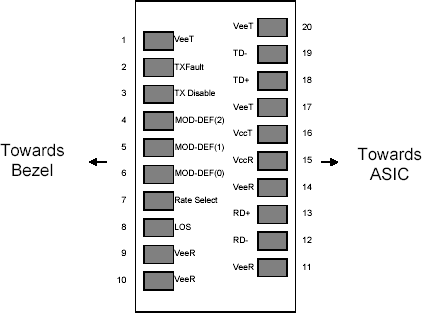
Figure 1. Diagram of host board connector block pin numbers and names
+3.3V Volt Electrical Power Interface
The product has an input voltage range of 3.3 V +/- 5%. The 4 V maximum voltage is not allowed for continuous operation.
|
Parameter |
Symbol |
Min. |
Typical |
Max. |
Units |
Notes/Conditions |
|
Supply Current |
Is |
320 |
375 |
mA |
1.2W max power over full range of voltage and temperature. See caution note below |
|
|
Input Voltage |
Vcc |
3.13 |
3.3 |
3.47 |
V |
Referenced to GND |
|
Surge Current |
Isurge |
30 |
mA |
Hot plug above steady state current. See caution note |
Table 2. +3.3 Volt electrical power interface
Caution:
Power consumption and surge current are higher than the specified values in the SFP MSA.
Low-Speed Signals
MOD_DEF(1) (SCL) and MOD_DEF(2) (SDA), are open drain CMOS signals. Both MOD_ DEF(1) and MOD_DEF(2) must be pulled up to host_Vcc.
|
Parameter |
Symbol |
Min. |
Max. |
Units |
Notes/Conditions |
|
SFP Output LOW |
VOL |
0 |
0.5 |
V |
4.7k to 10k pull-up to host_Vcc. |
|
SFP Output HIGH |
VOH |
host_Vcc -0.5 |
host_Vcc + 0.3 |
V |
4.7k to 10k pull-up to host_Vcc. |
|
SFP Input LOW |
VIL |
0 |
0.8 |
V |
4.7k to 10k pull-up to Vcc. |
|
SFP Input HIGH |
2 |
Vcc + 0.3 V |
V |
4.7k to 10k pull-up to Vcc. |
Table 3. Low-speed signals, electronic characteristics
High-Speed Electrical Interface
All high-speed signals are AC-coupled internally.
|
Transmission Line-SFP |
||||||
|
Parameter |
Symbol |
Min. |
Typical |
Max. |
Units |
Notes/Conditions |
|
Line Frequency |
fL |
125 |
MHz |
5-level encoding, per IEEE 802.3 |
||
|
Tx Output Impedance |
Zout,TX |
100 |
Ohm |
Differential |
||
|
Rx Input Impedance |
Zin,RX |
100 |
Ohm |
Differential |
||
Table 4. High-speed electrical interface, transmission line-SFP
|
Host-SFP |
||||||
|
Parameter |
Symbol |
Min. |
Typical |
Max. |
Units |
Notes/Conditions |
|
Single ended data input swing |
Vinsing |
250 |
1200 |
mV |
Single ended |
|
|
Single ended data output swing |
Voutsing |
350 |
100 |
800 |
mV |
Single ended |
|
Rise/Fall Time |
Tr,Tf |
175 |
psec |
20%-80% |
||
|
Tx Input Impedance |
Zin |
50 |
Ohm |
Single ended |
||
|
Rx Output Impedance |
Zout |
50 |
Ohm |
Single ended |
||
Table 5. High-speed electrical interface, host-SFP
General Specifications
|
Parameter |
Symbol |
Min. |
Typical |
Max. |
Units |
Notes/Conditions |
|
Data Rate |
BR |
10 |
1,000 |
Mb/s |
IEEE 802.3 compatible. |
|
|
Cable Length |
L |
100 |
m |
Category 5 UTP. BER <10-12 |
Table 6. General specifications
Notes:
- Clock tolerance is +/- 50ppm.
- By default, the FTCS-13RG-xxI is a full duplex device in preferred mastermode.
- Automatic crossover detection is enabled. External crossover cable is notrequired.
- 10/100/1000 BASE-T operation requires the host system to have an SGMII interface with no clocks.
Environmental Specifications
The product has a temperature range from -40°C to +85°C case temperature as specified in Table 7.
|
Parameter |
Symbol |
Min. |
Typical |
Max. |
Units |
Notes/Conditions |
|
Operating Temperature |
Top |
-40 |
85 |
°C |
Case temperature |
|
|
Storage Temperature |
Tsto |
-40 |
100 |
°C |
Ambient temperature |
Table 7. Environmental specifications
Serial ID Memory Contents
|
Data Address |
Length (Byte) |
Name of Length |
Description and Contents |
|
Base ID Fields |
|||
|
0 |
1 |
Identifier | |