

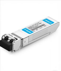
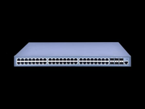
产品特点 / Product Features
10Gb/s serial optical interface compliant to 802.3ae 10GBASE-LR
Electrical interface compliant to SFF-8431 specifications for
enhanced 8.5 and 10 Gigabit small form factor pluggable module “SFP+”
1310nm DFB transmitter, PIN photo-detector
2-wire interface for management specifications compliant with SFF
8472 digital diagnostic monitoring interface for optical transceivers
ll-metal housing for superior EMI performance
Low power consumption
Advanced firmware allow customer system encryption information
to be stored in transceiver
Cost effective SFP+ solution, enables higher port densities and
greater bandwidth
RoHS compliant
Operating case temperature range:
Commercial:0 to 70 deg ℃
Industrial: -40 to 85 deg ℃
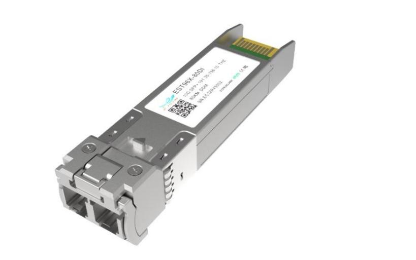
应用场景 / Applications
High-speed storage area networks
Computer cluster cross-connect
Custom high-speed data pipes
产品概述 / Description
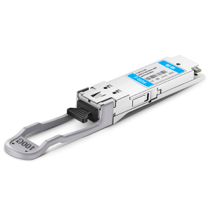
This 1310nm DFB 10Gigabit SFP+ transceiver is designed to transmit and receive optical data over single mode optical fiber for link length 10km.
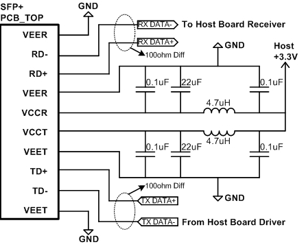
The SFP+ LR module electrical interface is compliant to SFI electrical specifications. The transmitter input and receiver output impedance is 100 Ohms differential. Data lines are internally AC coupled. The module provides differential termination and reduce differential to common mode conversion for quality signal termination and low EMI. SFI typically operates over 200 mm of improved FR4 material or up to about 150mmof standard FR4 with one connector.
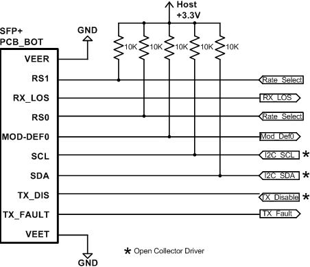
The transmitter converts 10Gbit/s serial CML electrical data into serial optical data compliant with the 10GBASE-LR standard. An open collector compatible Transmit Disable (Tx_Dis) is provided. A logic “1,” or no connection on this pin will disable the laser from transmitting. A logic “0” on this pin provides normal operation. The transmitter has an internal automatic power control loop (APC) to ensure constant optical power output across supply voltage and temperature variations. An open collector compatible Transmit Fault (TFault) is provided. TX_Fault is a module output contact that when high, indicates that the module transmitter has detected a fault condition related to laser operation or safety. The TX_Fault output contact is an open drain/collector and shall be pulled up to the Vcc_Host in the host with a resistor in the range 4.7-10 kΩ. TX_Disable is a module input contact. When TX_Disable is asserted high or left open, the SFP+ module transmitter output shall be turned off. This contact shall be pulled up to VccT with a 4.7 kΩ to 10 kΩ resistor
The receiver converts 10Gbit/s serial optical data into serial PECL/CML electrical data. An open collector compatible Loss of Signal is provided. Rx_LOS when high indicates an optical signal level below that specified in the relevant standard. The Rx_LOS contact is an open drain/collector output and shall be pulled up to Vcc_Host in the host with a resistor in the range 4.7-10 kΩ, or with an active termination. Power supply filtering is recommended for both the transmitter and receiver. The Rx_LOS signal is intended as a preliminary indication to the system in which the SFP+ is installed that the received signal strength is below the specified range. Such an indication typically points to non-installed cables, broken cables, or a disabled, failing or a powered off transmitter at the far end of the cable.
推荐应用电路 / Proposed Application Schematics
功能框图 / Functional Block Diagram
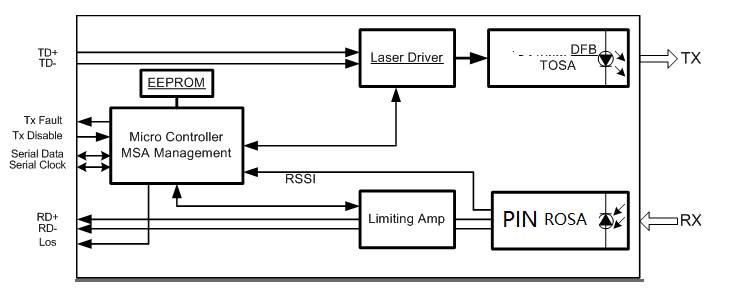
模块由发射、接收与控制三部分组成:发射侧由 MCU 通过 LD Bias / MOD-DEF 控制激光器驱动器(LD Driver),驱动激光器输出光信号;接收侧由光电探测器(内置跨阻放大器 TIA)与后级限幅放大器(Post Amp)恢复电信号;MCU 经 I2C(SDA/SCL)对外提供温度、电压、偏置电流、收发光功率等数字诊断信息,并处理 TX Disable、TX Fault、LOS 等控制与告警信号。
技术参数 / Specifications
绝对最大额定值 / Absolute Maximum Ratings
These values represent the damage threshold of the module. Stress in excess of any of the individual Absolute Maximum Ratings can cause immediate catastrophic damage to the module even if all other parameters are within Recommended Operating Conditions.
| Parameter | Symbol | Min | Max | Units |
|---|---|---|---|---|
| Power Supply Voltage | Vcc | 0 | 3.6 | V |
| Storage Temperature | Tc | -40 | 85 | C |
| Operating Case Temperature | Tc | 0 | 70 | C |
| TI | -40 | 85 | ||
| Relative Humidity | RH | 5 | 95 | % |
| RX Input Average Power | Pmax | 0 | dBm |
Note:
Exceeding any of these values may immediately damage the device.
推荐工作条件 / Recommended Operating Conditions
Recommended Operating Environment specifies parameters for which the electrical and optical characteristics hold unless otherwise noted.
| Parameter | Symbol | Min | Typ | Max | Units |
|---|---|---|---|---|---|
| Power Supply Voltage | Vcc | 3.135 | 3.3 | 3.465 | V |
| Power Supply Current | Icc | 350 | mA | ||
| Operating Case Temperature | TC | 0 | 25 | 70 | C |
| TC | -40 | 25 | 85 |
光学特性 / Optical Characteristics
| Parameters | Unit | Values |
|---|---|---|
| Operating Reach | m | 10K |
| Transmitter | ||
| Center wavelength (range) | nm | 1260 -1355 |
| Side Mode Suppression Ratio (min) | dB | 30 |
| Launched power | ||
| – maximum (Average) | dBm | 0.5 |
| – minimum (Average) | dBm | -8.2 |
| – OMA(min) | dBm | -5.2 |
| – OMA-TDP (min) | dBm | -6.2 |
| Transmitter and dispersion penalty (max) | dB | 3.2 |
| Average launch power of OFF transmitter (max) | dBm | -30 |
| Extinction ratio (min) | dB | 3.5 |
| RIN12 OMA (max) | dB/Hz | -128 |
| Optical Return Loss Tolerance (min) | dB | 12 |
| Receiver | ||
| Center wavelength (range) | nm | 1260-1620 |
| Receive overload (max) in average power(note 1) | dBm | 0.5 |
| Receive sensitivity (min) in average power(note 1) | dBm | -14.4 |
| Receiver sensitivity (max) in OMA (note 2) | dBm | -12.6 |
| Receiver Reflectance (max) | dB | -12 |
| Stressed receiver sensitivity (max) in OMA(note 2) | dBm | -10.3 |
| Vertical eye closure penalty (min)(note 3) | dB | 2.2 |
| Los Assert(min) | dBm | -30 |
| Los Dessert(max) | dBm | -12 |
| Los Hysteresis(min) | dB | 0.5 |
| Stressed eye jitter (min)(note 2) | UIp-p | 0.3 |
| Receive electrical 3dB upper cutoff frequency (max) | GHz | 12.3 |
| Receiver power (damage, Max) | dBm | 1.5 |
Note:
Average optical power shall be measured using the methods specified in TIA/EIA-455-95.
Receiver sensitivity is informative. Stressed receiver sensitivity shall be measured with conformance test signal for BER =1x 10-12.
Vertical eye closure penalty and stressed eye jitter are the test conditions for measuring stressed receiver sensitivity. They are not the required characteristic of the receiver.
Power budget is defined as the different between the Rx sensitivity and the Tx output power of the interface.
Path penalty is intended as the power penalty of the interface between back-to-back and the maximum applied dispersion.
数字诊断功能 / Digital Diagnostic Functions
The following digital diagnostic characteristics are defined over the Recommended Operating Environment unless otherwise specified. It is compliant to SFF8472 Rev10.2 with internal calibration mode. For external calibration mode please contact our sales stuff.
| Parameter | Symbol | Min | Max | Unit | Notes |
|---|---|---|---|---|---|
| Temperature monitor absolute error | DMI_Temp | -3 | 3 | Deg C | Over operating temp |
| Laser power monitor absolute error | DMI_TX | -3 | 3 | dB | |
| RX power monitor absolute error | DMI_RX | -3 | 3 | dB | -1dBm to -15dBm range |
| Supply voltage monitor absolute error | DMI_VCC | -0.08 | 0.08 | V | Full operating range |
| Bias current monitor | DMI_Ibias | -10% | 10% | mA |
电特性 / Electrical Characteristics
The following electrical characteristics are defined over the Recommended Operating Environment unless otherwise specified.
| Parameter | Symbol | Min | Typ | Max | Unit | Notes |
|---|---|---|---|---|---|---|
| Data Rate | / | 10.3125 | Gbps | |||
| Power Consumption | / | 800 | 1000 | mW | ||
| Transmitter | ||||||
| Single Ended Output Voltage Tolerance |
/ | -0.3 | 4 | V | ||
| C common mode voltage tolerance | / | 15 | mV | |||
| Tx Input Diff Voltage | VI | 180 | 800 | mV | ||
| Tx Fault | VoL | -0.3 | 0.4 | V | At 0.7mA | |
| Data Dependent Input Jitter | DDJ | 0.1 | UI | |||
| Data Input Total Jitter | TJ | 0.28 | UI | |||
| Receiver | ||||||
| Single Ended Output Voltage Tolerance |
/ | -0.3 | 4 | V | ||
| Rx Output Diff Voltage | Vo | 300 | 850 | mV | ||
| Rx Output Rise and Fall Time | Tr/Tf | 30 | ps | 20% to 80% | ||
| Total Jitter | TJ | 0.7 | UI | |||
| Deterministic Jitter | DJ | 0.42 | UI | |||
控制与状态 I/O 时序特性 / Control and Status I/O Timing Characteristics
Timing characteristics of control and status I/O are included in Table 8, which is also defined in SFF-8431.
| Parameter | Symbol | Min | Max | Unit | Condition |
|---|---|---|---|---|---|
| TX Disable Assert Time | t_off | 10 | μs | Time from rising edge of TX Disable to when the optical output falls below 10% of nominal | |
| TX Disable Negate Time | t_on | 1 | ms | Time from falling edge of TX Disable to when the modulated optical output rises above 90% of nominal | |
| Time to initialize,including reset of TX_Fault | t_init | 300 | ms | From power on or negation of TX Fault using TX Disable | |
| TX Fault Assert Time | t_fault | 100 | μs | Time from fault to TX fault on | |
| TX Disable to reset | t_reset | 10 | μs | Time TX Disable must be held high to reset TX fault | |
| LOS Assert Time | t_loss_on | 100 | μs | Time from LoS state to RX LOS assert | |
| LOS Deassert Time | t_loss_off | 100 | μs | Time from non-LOS state to RX LOS deassert | |
| Rate-Select Change Time | t_ratesel | 10 | μs | Time from rising or falling edge of Rate Select input until receiver bandwidth is in conformance with appropriate specification | |
| Serial lD Clock Rate | t_serial_clock | 100 | kHz |
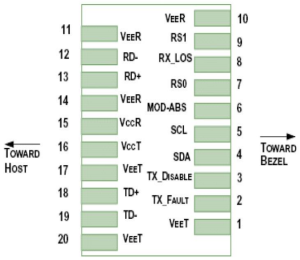
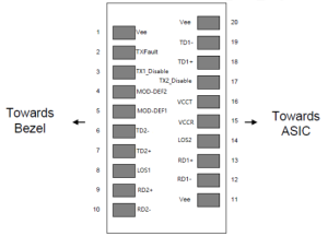
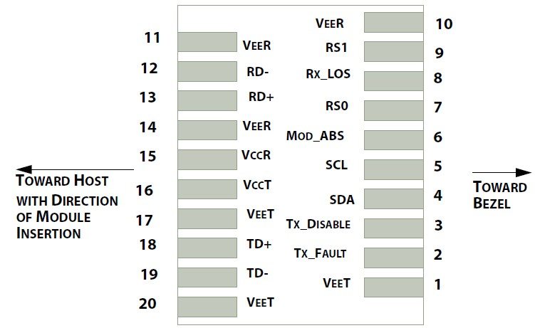
引脚定义 / Pin Assignment and Description
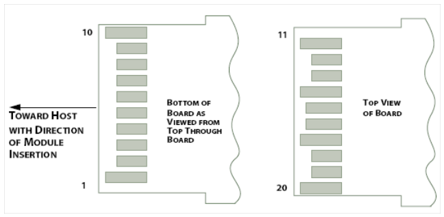
| PIN Definition | ||||
|---|---|---|---|---|
| PIN | Logic | Symbol | Description | Notes |
| 1 | VeeT | Module Transmitter Ground | 1 | |
| 2 | LVTTL-O | TX_Fault | Module Transmitter Fault | |
| 3 | LVTTL-I | TX_Dis | Transmitter Disable; Turns off transmitter laser output | |
| 4 | LVTTL-I/O | SDA | 2-Wire Serial Interface Data Line | 2 |
| 5 | LVTTL-I | SCL | 2-Wire Serial Interface Clock | 2 |
| 6 | MOD_DEF0 | Module Definition, Grounded in the module | ||
| 7 | LVTTL-I | RS0 | Receiver Rate Select | |
| 8 | LVTTL-O | RX_LOS | Receiver Loss of Signal Indication Active LOW | |
| 9 | LVTTL-I | RS1 | Transmitter Rate Select (not used) | |
| 10 | VeeR | Module Receiver Ground | 1 | |
| 11 | VeeR | Module Receiver Ground | 1 | |
| 12 | CML-O | RD- | Receiver Inverted Data Output | |
| 13 | CML-O | RD+ | Receiver Data Output | |
| 14 | VeeR | Module Receiver Ground | 1 | |
| 15 | VccR | Module Receiver 3.3 V Supply | ||
| 16 | VccT | Module Receiver 3.3 V Supply | ||
| 17 | VeeT | Module Transmitter Ground | 1 | |
| 18 | CML-I | TD+ | Transmitter Non-Inverted Data Input | |
| 19 | CML-I | TD- | Transmitter Inverted Data Input | |
| 20 | VeeT | Module Transmitter Ground | 1 | |
Note:
Module ground pins GND are isolated from the module case.
Shall be pulled up with 4.7K-10Kohms to a voltage between 3.15V and 3.45V on the host board.
机械规格 / Mechanical Specifications
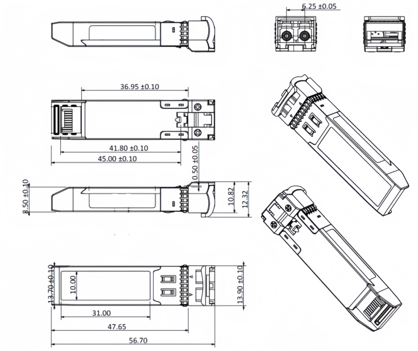
Comply to SFF-8432 rev. 5.0, the improved Pluggable form factor specification.
ESD 静电防护 / ESD
This transceiver is specified as ESD threshold 2kV for all electrical input pins, tested per MIL-STD-883, Method 3015.4 /JESD22-A114-A (HBM). However, normal ESD precautions are still required during the handling of this module. This transceiver is shipped in ESD protective packaging. It should be removed from the packaging and handled only in an ESD protected environment.
激光安全 / Laser Safety
This is a Class 1 Laser Product according to IEC 60825-1:1993:+A1:1997+A2:2001. This product complies with 21 CFR 1040.10 and 1040.11 except for deviations pursuant to Laser Notice No. 50, dated (July 26, 2001).
订购信息 / Ordering Information
| Model | Specification Description |
|---|---|
| BYCS-131X-10D | SFP+ DAUL, 10.3125G, 1310nm, 10km, with DDM, 0 ~ 70℃, 3.3V, LC |
| BYCS-131X-10DI | SFP+ DAUL, 10.3125G, 1310nm, 10km, with DDM, -40 ~ 85℃, 3.3V, LC |
地区:中国四川天府新区
服务区域:全球
联系方式:
企业电话:028-85255257 | 企业传真:028-85977702 | 企业手机:19081343401
Site:https://www.f-tone.com
人事部:hr@f-tone.com | 市场部:sales@f-tone.com | 技术支持:support@f-tone.com
本产品为光模块产品线,详细信息,请联系我们的销售人员,谢谢!
Important Notice
Performance figures, data and any illustrative material provided in this data sheet are typical and must be specifically confirmed in writing by F-tone Networks before they become applicable to any particular order or contract. In accordance with the F-tone Networks policy of continuous improvement specifications may change without notice. The publication of information in this data sheet does not imply freedom from patent or other protective rights of F-tone Networks or others. Further details are available from any F-tone Networks sales representative.
