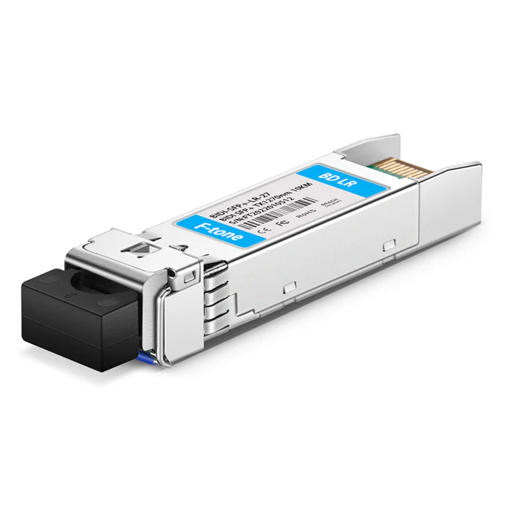
10.3Gbps SFP+ BIDI Transceiver, Single Mode, 20km Reach
1330nm TX / 1270nm RX
FTCS-B331X-20Dxx
Product Features
- Supports up to 10.7Gbps bit rates
- Hot-pluggable SFP+ footprint
- 1330nm DFB laser and PIN photodiode, Up to 20km for SMF transmission
- Compliant with SFP+ MSA and SFF-8472 with single LC receptacle
- Compatible with RoHS
- Single +3.3V power supply
- Real Time Digital Diagnostic Monitoring
- Operating case temperature:
Standard: 0 to +70°C
Industrial: -40 to +85°C
Applications
- 10Gbps Optical systems
- 10GBASE-LR at 10.3125Gbps
- 10GBASE-LW at 9.953Gbps
- LTE systems
- Other Optical links
Description
The SFP+ transceivers are high performance, cost effective modules supporting data rate of 10Gbps and 20km transmission distance with SMF.
The transceiver consists of three sections: a DFB laser transmitter, a PIN photodiode integrated with a trans-impedance preamplifier (TIA) and MCU control unit. All modules satisfy class I laser safety requirements.
The transceivers are compatible with SFP Multi-Source Agreement and SFF-8472 digital diagnostics functions.
Temp
Vcc
LD Bias
Tx Power
Rx Power
TD+/-
TxFault
TxDis
LOS
RD+/-
POWER
SCL
SDA
LD Driver
LD
PIN+TIA
I2C Controller
Post Amp
EEPROM
ADC/DAC
Transceiver functional diagram
Absolute Maximum Ratings
|
Parameter |
Symbol |
Min |
Max |
Unit |
|
Supply Voltage |
Vcc |
-0.5 |
4.5 |
V |
|
Storage Temperature |
Ts |
-40 |
+85 |
°C |
|
Operating Humidity |
– |
5 |
85 |
% |
Recommended Operating Conditions
|
Parameter |
Symbol |
Min |
Typical |
Max |
Unit |
|
|
Operating Case Temperature |
Standard |
Tc |
0 |
+70 |
°C |
|
|
Extended |
-20 |
+80 |
°C |
|||
|
Industrial |
-40 |
+85 |
°C |
|||
|
Power Supply Voltage |
Vcc |
3.135 |
3.30 |
3.465 |
V |
|
|
Power Supply Current |
Icc |
350 |
mA |
|||
|
Data Rate |
1.0 |
10.3 |
10.7 |
Gbps |
||
Optical and Electrical Characteristics
|
Parameter |
Symbol |
Min |
Typical |
Max |
Unit |
Notes |
||
|
Transmitter |
||||||||
|
Centre Wavelength |
λc |
1320 |
1330 |
1340 |
nm |
|||
|
Spectral Width(-20dB) |
Δλ |
1 |
nm |
|||||
|
Side-Mode Suppression Ratio |
SMSR |
30 |
– |
dB |
||||
|
Average Output Power |
Pout |
-3 |
+2 |
dBm |
1 |
|||
|
Extinction Ratio |
ER |
3.5 |
dB |
|||||
|
Data Input Swing Differential |
VIN |
180 |
850 |
mV |
2 |
|||
|
Input Differential Impedance |
ZIN |
90 |
100 |
110 |
Ω |
|||
|
TX Disable |
Disable |
2.0 |
Vcc |
V |
||||
|
Enable |
0 |
0.8 |
V |
|||||
|
TX Fault |
Fault |
2.0 |
Vcc |
V |
||||
|
Normal |
0 |
0.8 |
V |
|||||
|
Receiver |
||||||||
|
Centre Wavelength |
λc |
1260 |
1270 |
1280 |
nm |
|||
|
Receiver Sensitivity |
-15 |
dBm |
3 |
|||||
|
Receiver Overload |
0.5 |
dBm |
3 |
|||||
|
LOS De-Assert |
LOSD |
-16 |
dBm |
|||||
|
LOS Assert |
LOSA |
-30 |
dBm |
|||||
|
LOS Hysteresis |
0.5 |
dB |
||||||
|
Data Output Swing Differential |
Vout |
300 |
900 |
mV |
4 |
|||
|
LOS |
High |
2.0 |
Vcc |
V |
||||
|
Low |
0.8 |
V |
||||||
Notes:
1. The optical power is launched into SMF.
2. PECL input, internally AC-coupled and terminated.
3. Measured with a PRBS 231-1 test pattern @10312Mbps, BER ≤1×10-12.
4. Internally AC-coupled.
Timing and Electrical
|
Parameter |
Symbol |
Min |
Typical |
Max |
Unit |
|
Tx Disable Negate Time |
t_on |
1 |
ms |
||
|
Tx Disable Assert Time |
t_off |
10 |
µs |
||
|
Time To Initialize, including Reset of Tx Fault |
t_init |
300 |
ms |
||
|
Tx Fault Assert Time |
t_fault |
100 |
µs |
||
|
Tx Disable To Reset |
t_reset |
10 |
µs |
||
|
LOS Assert Time |
t_loss_on |
100 |
µs |
||
|
LOS De-assert Time |
t_loss_off |
100 |
µs |
||
|
Serial ID Clock Rate |
f_serial_clock |
100 |
400 |
KHz |
|
|
MOD_DEF (0:2)-High |
VH |
2 |
Vcc |
V |
|
|
MOD_DEF (0:2)-Low |
VL |
0.8 |
V |
Diagnostics
|
Parameter |
Range |
Unit |
Accuracy |
Calibration |
|
Temperature |
0 to +70 |
°C |
±3°C |
Internal |
|
-20 to +80 |
||||
|
-40 to +85 |
||||
|
Voltage |
3.0 to 3.6 |
V |
±3% |
Internal |
|
Bias Current |
0 to 100 |
mA |
±10% |
Internal |
|
TX Power |
-3 to +2 |
dBm |
±3dB |
Internal |
|
RX Power |
-15 to +1 |
dBm |
±3dB |
Internal |
Digital Diagnostic Memory Map
The transceivers provide serial ID memory contents and diagnostic information about the present operating conditions by the 2-wire serial interface (SCL, SDA).
The diagnostic information with internal calibration or external calibration all are implemented, including received power monitoring, transmitted power monitoring, bias current monitoring, supply voltage monitoring and temperature monitoring.
The digital diagnostic memory map specific data field defines as following.