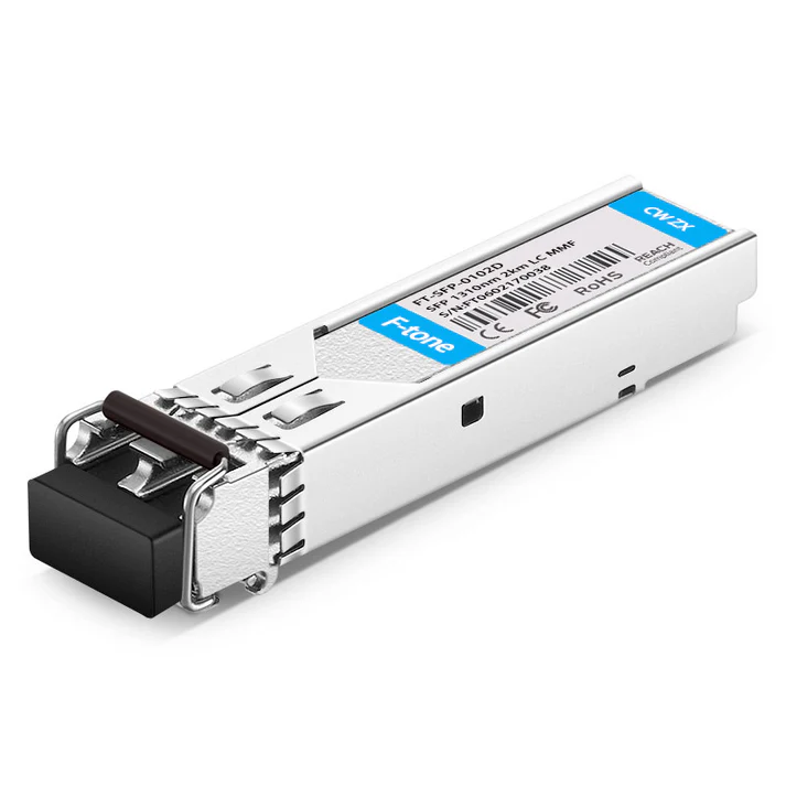
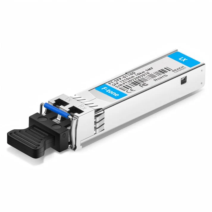
SFP GE-100FX SGMII Optical Transceiver
Features:
- 1310nm FP laser transmitter
- Duplex LCconnector
- RoHS compliant and Lead Free
- Up to 2 Km on 50/125μm MMF
- Single +3.3V Power Supply
- Very low EMI and excellent ESD protection
- Built-in PHY supporting SGMII Interface
- Operating case temperature: 0 to +70°C
Applications:
- Fast Ethernet
- Hot-Pluggable
- 100BASE-FX operation
- Other Optical Links
Description:
The transceiver is a high performance, cost effective module which have a Duplex LC optics interface.
Standard AC coupled CML for high speed signal and LVTTL control and monitor signals.
The receiver section uses a PIN receiver and the transmitter uses 1310 nm FP laser, up to 12dB link budge ensure this module Fast Ethernet 2km application with PHY supporting SGMII interface make it support Fast Ethernet in Gigabit Ethernet port.
Absolute Maximum Ratings
|
Parameter |
Symbol |
Min. |
Typical |
Max. |
Unit |
|
Storage Temperature |
TS |
-40 |
+85 |
°C |
|
|
Supply Voltage |
VCCT, R |
-0.5 |
4 |
V |
|
|
Relative Humidity |
RH |
0 |
85 |
% |
|
|
Case Operating Temperature |
TC |
0 |
70 |
C |
Recommended Operating Environment:
|
Parameter |
Symbol |
Min. |
Typical |
Max. |
Unit |
|
Caseoperating Temperature |
TC |
0 |
+70 |
°C |
|
|
Supply Voltage |
VCCT, R |
3.0 |
3.6 |
V |
|
|
Power Supply Rejection |
100 |
mVP-P |
|||
|
Data Rate |
BR |
155 |
Mb/s |
Electrical Characteristics
|
Parameter |
Symbol |
Min. |
Typical |
Max. |
Unit |
Note |
|
Supply Voltage |
Vcc |
3.0 |
3.30 |
3.60 |
V |
|
|
Supply Current |
Icc |
360 |
mA |
|||
|
Maximum Power |
Pmax |
1.0 |
W |
|||
|
Transmitter Section: |
||||||
|
Input differential impedance |
Rin |
90 |
100 |
110 |
Ω |
1 |
|
Single ended data input swing |
Vin PP |
200 |
1200 |
mVp-p |
||
|
Transmit Disable Voltage |
VD |
Vcc – 1.3 |
Vcc |
V |
2 |
|
|
Transmit Enable Voltage |
VEN |
Vee |
Vee+ 0.8 |
V |
||
|
Transmit Disable Assert Time |
Tdessert |
10 |
us |
|||
|
Receiver Section: |
||||||
|
Single ended data output swing |
Vout,pp |
300 |
1000 |
mv |
3 |
|
|
Data output rise time |
tr |
150 |
ps |
4 |
||
|
Data output fall time |
tf |
150 |
ps |
4 |
||
|
LOS Fault |
Vlosfault |
Vcc – 0.5 |
VCC_host |
V |
5 |
|
|
LOS Normal |
Vlos norm |
Vee |
Vee+0.5 |
V |
5 |
|
|
Power Supply Rejection |
PSR |
100 |
mVpp |
6 |
Note:
- AC coupled.
- Or open circuit.
- Into 100 ohm differential termination. 4. 20 – 80 %
- LOS is LVTTL. Logic 0 indicates normal operation; logic 1 indicates no signal detected.
- All transceiver specifications are compliant with a power supply sinusoidal modulation of 20 Hz to 1.5MHz up to specified value applied through the power supply filtering network shown on page 23 of the Small Form-factor Pluggable (SFP) Transceiver Multi-Source Agreement (MSA), September 14, 2000.
Optical Characteristics
|
Parameter |
Symbol |
Min. |
Typical |
Max. |
Unit |
Note |
|
Transmitter Section: |
||||||
|
Center Wavelength |
λc |
1270 |
1310 |
1360 |
nm |
1 |
|
Spectral Width |
σ |
7 |
nm |
|||
|
Optical Output Power |
Pout |
-18 |
-10 |
dBm |
2 |
|
|
Optical Rise/Fall Time |
tr / tf |
160 |
ps |
3 |
||
|
Extinction Ratio |
ER |
9 |
dB |
|||
|
Eye Mask for Optical Output |
Compliant with Eye Mask Defined in IEEE 802.3 standard |
|||||
|
Receiver Section: |
||||||
|
Optical Input Wavelength |
λ |
1100 |
1670 |
nm |
||
|
RX Sensitivity |
Sen |
-31 |
dBm |
4.5 |
||
|
Receiver Overload |
Pol |
-3 |
dBm |
4.5 |
||
|
RX_LOS Assert |
LOS A |
-45 |
dBm |
|||
|
RX_LOS Deassert |
LOS D |
-34 |
dBm |
|||
|
RX_LOS Hysteresis |
LOS H |
0.5 |
dB |
|||
|
Total Jitter(SGMII Series Interface) |
TJ |
0.43 |
UI |
|||
Note
- Also specified to meet curves in FC-PI 13.0 Figures 18 and 19, which allow trade-off between wavelength spectralwidth.
- Class 1 Laser Safety per FDA/CDRH and EN (IEC) 60825 regulations.
- Unfiltered, 20-80%. Complies with IEEE 802.3 (Gig. E), FC 1x and 2x eye masks when filtered.
- Measured with conformance signals defined in FC-PI 13.0 specifications.
- Measured with PRBS 27-1 at 10-12 BER
Pin Assignment:
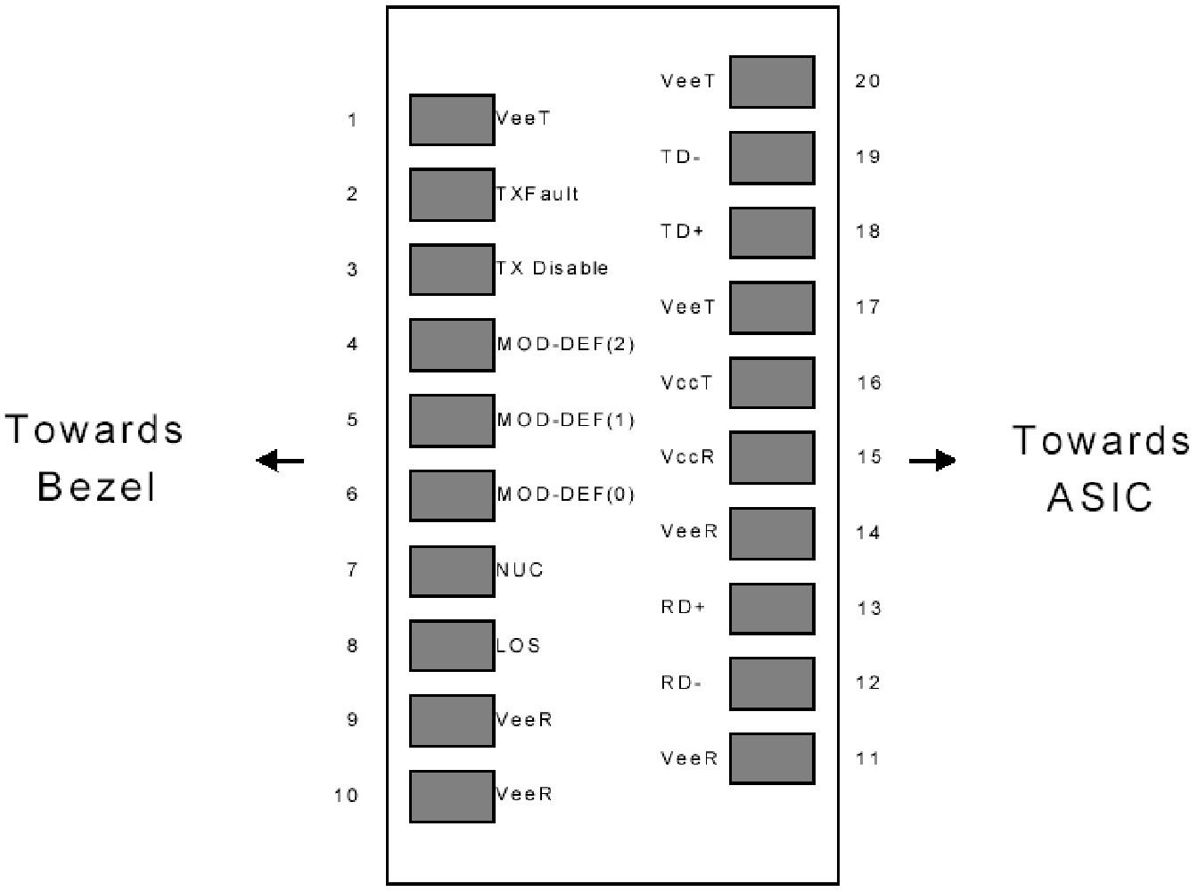
Diagram of Host Board Connector Block Pin Numbers and Names
Pin Description:
|
Pin No |
Name |
Function |
Plug Seq |
Notes |
|
1 |
VeeT |
Transmitter Ground |
1 |
1 |
|
2 |
TX Fault |
Transmitter Fault Indication |
3 |
|
|
3 |
TX Disable |
Transmitter Disable |
3 |
2 |
|
4 |
MOD-DEF2 |
Module Definition |
2 |
3 |
|
5 |
MOD-DEF1 |
Module Definition 1 |
3 |
3 |
|
6 |
MOD-DEF0 |
Module Definition 0 |
3 |
3 |
|
7 |
Rate Select |
Not Connected |
3 |
4 |
|
8 |
LOS |
Loss of Signal |
3 |
5 |
|
9 |
VeeR |
Receiver Ground |
1 |
1 |
|
10 |
VeeR |
Receiver Ground |
1 |
1 |
|
11 |
VeeR |
Receiver Ground |
1 |
1 |
|
12 |
RD- |
Inv. Received Data Out |
3 |
6 |
|
13 |
RD+ |
Received Data Out |
3 |
6 |
|
14 |
VeeR |
Receiver Ground |
3 |
1 |
|
15 |
VccR |
Receiver Power |
2 |
1 |
|
16 |
VccT |
Transmitter Power |
2 |
|
|
17 |
VeeT |
Transmitter Ground |
1 |
|
|
18 |
TD+ |
Transmit Data In |
3 |
6 |
|
19 |
TD- |
Inv. Transmit In |
3 |
6 |
|
20 |
VeeT |
Transmitter Ground |
1 |
Notes:
-
- Circuit ground is internally isolated from chassis ground.
- Laser output disabled on TDIS >2.0V or open, enabled on TDIS <0.8V.
- Should be pulled up with 4.7k – 10 kohms on host board to a voltage between 2.0V and
3.6V.MOD_DEF(0) pulls line low to indicate module is plugged in.
-
- Rate select is not used
- LOS is open collector output. Should be pulled up with 4.7k – 10 kohms on host board to a voltage between 2.0V and 3.6V. Logic 0 indicates normal operation; logic 1 indicates loss of signal.
- AC Coupled
Serial ID Memory Contents:
|
Data Address |
Length (Byte) |
Name of Length |
Description and Contents |
|
Base ID Fields |
|||
|
0 |
1 |
Identifier |
Type of Serial transceiver (03h=SFP) |
|
1 |
1 |
Reserved |
Extended identifier of type serial transceiver (04h) |
|
2 |
1 |
Connector | |