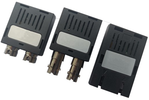
FTAT-xx24-xxxx 2.5G 2X5 SFF Transceiver Module
Product Description
F-tone’s FTAT-xx24-xxxx series of transceiver modules are the perfect solution for high-speed communication networks. These transceiver modules support data rates up to 3.1Gbps. The module is fully compliant with the 2X5 standard package defined by the Small Form Factor Multi-Sourcing Agreement (MSA).
These transceiver modules provides the system designer with Telecom, Datacom, Digital Video and other Fibre Channel applications.
Product Features
- FP/DFB Laser Diode Transmitter
- Up to 80km on 9/125μm SMF
- 3.3V power supply
- LC duplex optical interface
- CML Differential Input, Output and LVTTL signal detect
- Class 1 Laser International Safety Standard IEC 825 Compliant
- Operating case temperature range (Standard: 0 to +70°C) or (Industrial: -40°C to +85°C)
Applications
- Fiber Channel
- Digital Video system
- Other optic link
Absolute Maximum Ratings
Operating of the transceiver beyond the Absolute Conditions Listed in Table 1 will degrade or damage the product. It’s not implied that the product would function above the recommended operating environment, it’s possible to reduce the reliability and lifetime of device if Recommended Operating Environment is exceeded (Refer to table 2).
Table 1 – Absolute Maximum Conditions
| Parameter | Symbol | Min | Max | Units | Note |
|---|---|---|---|---|---|
| StorageTemperature | T ST |
-40 | +85 | ℃ | – |
| RelativeHumidity | RH | 5 | 95 | % | – |
| SupplyVoltage | V CC |
0 | +3.6 | V | – |
Table 2 – Recommended Operating Environment and Electrical Characteristics
| Parameter | Symbol | Min | Typ | Max | Units | Note |
|---|---|---|---|---|---|---|
| SupplyVoltage | V CC |
+3.1 | +3.3 | +3.5 | V | – |
| SupplyCurrent | Icc | – | – | 260 | mA | – |
| OperatingCaseTemperature | T OP |
0 | +70 | ℃ | 1 | |
| -40 | +85 | 2 | ||||
| DataRate | B | 100 | 2488 | 3100 | Mbps | – |
| Solderingtemperature | – | – | – | 350 | ℃ | 3 |
| Solderingduration | – | – | – | 10 | Sec | 3 |
Notes:
1. standard level
2. industrial level
3. Not recommended wave soldering.
Optical Parameters
Table 3 – FTAT-1324-02xx Transceiver Optical Characteristics
| Parameter | Symbol | Min | Typ | Max | Units | Note | |
|---|---|---|---|---|---|---|---|
| Transmitter | |||||||
| Datarate | B | 100 | 2488 | 3100 | Mbps | – | |
| OutputCenterWavelength | λc | 1260 | 1310 | 1360 | nm | – | |
| OutputSpectralwidth(RMS) | λ | – | – | 4 | nm | – | |
| AverageOpticalOutputPower | Po | -10 | – | -3 | dBm | 1,2 | |
| ExtinctionRatio | ER | 8 | – | – | dB | 1,2 | |
| OpticOutputEye:CompliantITU-TG.957 | 1,2 | ||||||
| Receiver | |||||||
| ReceiverSensitivity | P min |
– | – | -18 | dBm | 1,2 | |
| ReceiverSaturation | P max |
-3 | – | – | dBm | 1,2 | |
| OperationCenterWavelength | λc | 1260 | – | 1620 | nm | – | |
| D SD A |
eassert | PD | -35 | – | – | dBm | 1,2 |
| ssert | PA | – | – | -18 | dBm | 1,2 | |
| SDHysteresis | SDHYS | 0.5 | – | – | dB | – |
Notes:
Note 1: The optical power is launched into 9/125μm SMF.
Note 2: With a PRBS 223-1 test pattern @2488Mbps.
Table 4 – FTAT-1324-20xx Transceiver Optical Characteristics
| Parameter | Symbol | Min | Typ | Max | Units | Note | |
|---|---|---|---|---|---|---|---|
| Transmitter | |||||||
| Datarate | B | 100 | 2488 | 3100 | Mbps | – | |
| OutputCenterWavelength | λc | 1260 | 1310 | 1360 | nm | – | |
| OutputSpectralwidth(RMS) | λ | – | – | 4 | nm | – | |
| AverageOpticalOutputPower | Po | -5 | – | 0 | dBm | 1,2 | |
| ExtinctionRatio | ER | 8 | – | – | dB | 1,2 | |
| OpticOutputEye:CompliantITU-TG.957 | 1,2 | ||||||
| Receiver | |||||||
| ReceiverSensitivity | P min |
– | – | -18 | dBm | 1,2 | |
| ReceiverSaturation | P max |
-3 | – | – | dBm | 1,2 | |
| OperationCenterWavelength | λc | 1260 | – | 1620 | nm | – | |
| D SD A |
eassert | PD | -35 | – | – | dBm | 1,2 |
| ssert | PA | – | – | -18 | dBm | 1,2 | |
| SDHysteresis | SDHYS | 0.5 | – | – | dB | – |
Notes:
Note 1: The optical power is launched into 9/125μm SMF.
Note 2: With a PRBS 223-1 test pattern @2488Mbps.
Table 5 – FTAT-1324-40xx Transceiver Optical Characteristics
| Parameter | Symbol | Min | Typ | Max | Units | Note | |
|---|---|---|---|---|---|---|---|
| Transmitter | |||||||
| Datarate | B | 100 | 2488 | 3100 | Mbps | – | |
| OutputCenterWavelength | λc | 1260 | 1310 | 1360 | nm | – | |
| OutputSpectralwidth(-20dB) | λ | – | – | 1 | nm | – | |
| AverageOpticalOutputPower | Po | -3 | – | +2 | dBm | 1,2 | |
| ExtinctionRatio | ER | 8 | – | – | dB | 1,2 | |
| OpticOutputEye:CompliantITU-TG.957 | 1,2 | ||||||
| Receiver | |||||||
| ReceiverSensitivity | P min |
– | – | -20 | dBm | 1,2 | |
| ReceiverSaturation | P max |
-3 | – | – | dBm | 1,2 | |
| OperationCenterWavelength | λc | 1260 | – | 1620 | nm | – | |
| SD | Deassert | PD | -35 | – | – | dBm | 1,2 |
| Assert | PA | – | – | -20 | dBm | 1,2 | |
| SDHysteresis | SDHYS | 0.5 | – | – | dB | – |
Notes:
Note 1: The optical power is launched into 9/125μm SMF.
Note 2: With a PRBS 223-1 test pattern @2488Mbps.
Table 6 – FTAT-1524-20xx Transceiver Optical Characteristics
| Parameter | Symbol | Min | Typ | Max | Units | Note | |
|---|---|---|---|---|---|---|---|
| Transmitter | |||||||
| Datarate | B | 100 | 2488 | 3100 | Mbps | – | |
| OutputCenterWavelength | λc | 1480 | 1550 | 1580 | nm | – | |
| OutputSpectralwidth(-20dB) | λ | – | – | 1 | nm | – | |
| AverageOpticalOutputPower | Po | -5 | – | 0 | dBm | 1,2 | |
| ExtinctionRatio | ER | 8 | – | – | dB | 1,2 | |
| OpticOutputEye:CompliantITU-TG.957 | 1,2 | ||||||
| Receiver | |||||||
| ReceiverSensitivity | P min |
– | – | -18 | dBm | 1,2 | |
| ReceiverSaturation | P max |
-3 | – | – | dBm | 1,2 | |
| OperationCenterWavelength | λc | 1260 | – | 1620 | nm | – | |
| SD | Deassert | PD | -35 | – | – | dBm | 1,2 |
| Assert | PA | – | – | -18 | dBm | 1,2 | |
| SDHysteresis | SDHYS | 0.5 | – | – | dB | – |
Notes:
Note 1: The optical power is launched into 9/125μm SMF.
Note 2: With a PRBS 223-1 test pattern @2488Mbps.
Table 7 – FTAT-1524-40xx Transceiver Optical Characteristics
| Parameter | Symbol | Min | Typ | Max | Units | Note | |
|---|---|---|---|---|---|---|---|
| Transmitter | |||||||
| Datarate | B | 100 | 2488 | 3100 | Mbps | – | |
| OutputCenterWavelength | λc | 1480 | 1550 | 1580 | nm | – | |
| OutputSpectralwidth(-20dB) | λ | – | – | 1 | nm | – | |
| AverageOpticalOutputPower | Po | -3 | – | +2 | dBm | 1,2 | |
| ExtinctionRatio | ER | 8 | – | – | dB | 1,2 | |
| OpticOutputEye:CompliantITU-TG.957 | 1,2 | ||||||
| Receiver | |||||||
| ReceiverSensitivity | P min |
– | – | -20 | dBm | 1,2 | |
| ReceiverSaturation | P max |
-3 | – | – | dBm | 1,2 | |
| OperationCenterWavelength | λc | 1260 | – | 1620 | nm | – | |
| D SD A |
eassert | PD | -35 | – | – | dBm | 1,2 |
| ssert | PA | – | – | -20 | dBm | 1,2 | |
| SDHysteresis | SDHYS | 0.5 | – | – | dB | – |
Notes:
Note 1: The optical power is launched into 9/125μm SMF.
Note 2: With a PRBS 223-1 test pattern @2488Mbps.
Table 8 – FTAT-1524-80xx Transceiver Optical Characteristics
| Parameter | Symbol | Min | Typ | Max | Units | Note | |
|---|---|---|---|---|---|---|---|
| Transmitter | |||||||
| Datarate | B | 100 | 2488 | 3100 | Mbps | – | |
| OutputCenterWavelength | λc | 1480 | 1550 | 1580 | nm | – | |
| OutputSpectralwidth(-20dB) | λ | – | – | 1 | nm | – | |
| AverageOpticalOutputPower | Po | 0 | – | +5 | dBm | 1,2 | |
| ExtinctionRatio | ER | 8 | – | – | dB | 1,2 | |
| OpticOutputEye:CompliantITU-TG.957 | 1,2 | ||||||
| Receiver | |||||||
| ReceiverSensitivity | P min |
– | – | -26 | dBm | 1,2 | |
| ReceiverSaturation | P max |
-3 | – | – | dBm | 1,2 | |
| OperationCenterWavelength | λc | 1260 | – | 1620 | nm | – | |
| D SD A |
eassert | PD | -35 | – | – | dBm | 1,2 |
| ssert | PA | – | – | -26 | dBm | 1,2 | |
| SDHysteresis | SDHYS | 0.5 | – | – | dB | – |
Notes:
Note 1: The optical power is launched into 9/125μm SMF.
Note 2: With a PRBS 223-1 test pattern @1250Mbps.
Electrical Parameters
Table 9 – Transceiver Electrical Characteristics
| Parameter | Symbol | Min | Typ | Max | Units | Note |
|---|---|---|---|---|---|---|
| SupplyVoltage | V CC |
+3.1 | +3.3 | +3.5 | V | – |
| SupplyCurrent | I CC |
– | – | 260 | mA | – |
| Transmitter | ||||||
| DifferentialInputVoltage | Vin | 200 | – | 1000 | mV P-P |
– |
| InputDifferentialImpedance | Zin | 90 | 100 | 110 | Ω | – |
| Receiver | ||||||
| DifferentialOutputVoltage | V OUT |
100 | – | 1000 | mV P-P |
– |
| OutputDifferentialImpedance | Zout | 90 | 100 | 110 | Ω | – |
| SDOutputVoltage-Low | V OL |
0 | – | 0.8 | V | 1 |
| SDOutputVoltage-High | V OH |
2 | – | V CC |
V | 1 |
Note 1: LVTTL signal detect
Pin Definitions
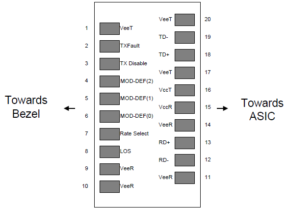
Table 10 – Connector Pin Assignment
| Pin# | PinName | Description | Note |
|---|---|---|---|
| 1 | VEER | ReceiverGround | – |
| 2 | VCCR | ReceiverPowerSupply | – |
| 3 | SD | SignalDetect. LVTTLoutput | 1 |
| 4 | RD- | Inv.ReceivedDataOut | – |
| 5 | RD+ | ReceivedDataOut | – |
| 6 | VCCT | TransmitterPowerSupply | – |
| 7 | VEET | TransmitterGround | – |
| 8 | TXDIS | TransmitterDisable | 2 |
| 9 | TD+ | TransmitDataIn | – |
| 10 | TD- | Inv.TransmitDataIn | – |
Note 1: LVTTL – Normal optical input levels to the receiver result in logic “0 or 1” output, pull-up 10kΩ resistor.
Note 2: This is an input that is used to shut down the transmitter optical output. Transmitter on in logic “0”.
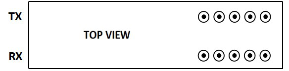
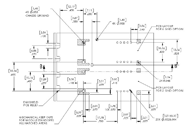
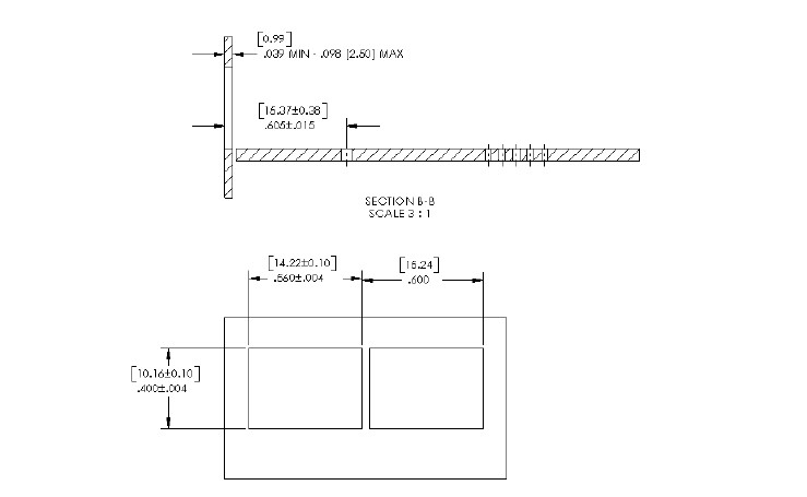
Recommended Board Layout Hole Pattern
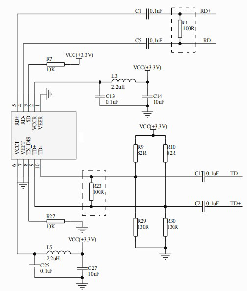
Recommended Circuit Schematic
Circuit Schematic: 3.3V SD LVTTL
Module Outline Drawing
Note: Specifications subject to change without notice.
Ordering Information
| Part Number | Product Description |
|---|---|
| FTAT-1324-02 | 2X5 SFF Transceiver, 1310nm, 2.5Gbps, 2km, 0°C~+70°C |
| FTAT-1324-02I | 2X5 SFF Transceiver, 1310nm, 2.5Gbps, 2km, -40°C~+85°C |
| FTAT-1324-20 | 2X5 SFF Transceiver, 1310nm, 2.5Gbps, 20km, 0°C~+70°C |
| FTAT-1324-20I | 2X5 SFF Transceiver, 1310nm, 2.5Gbps, 20km, -40°C~+85°C |
| FTAT-1324-40 | 2X5 SFF Transceiver, 1310nm, 2.5Gbps, 40km, 0°C~+70°C |
| FTAT-1324-40I | 2X5 SFF Transceiver, 1310nm, 2.5Gbps, 40km, -40°C~+85°C |
| FTAT-1524-20 | 2X5 SFF Transceiver, 1550nm, 2.5Gbps, 20km, 0°C~+70°C |
| FTAT-1524-20I | 2X5 SFF Transceiver, 1550nm, 2.5Gbps, 20km, -40°C~+85°C |
| FTAT-1524-40 | 2X5 SFF Transceiver, 1550nm, 2.5Gbps, 40km, 0°C~+70°C |
| FTAT-1524-40I | 2X5 SFF Transceiver, 1550nm, 2.5Gbps, 40km, -40°C~+85°C |
| FTAT-1524-80 | 2X5 SFF Transceiver, 1550nm, 2.5Gbps, 80km, 0°C~+70°C |
| FTAT-1524-80I | 2X5 SFF Transceiver, 1550nm, 2.5Gbps, 80km, -40°C~+85°C |
企业信息
| 项目 | 信息 |
|---|---|
| 公司名 | 北亿纤通 | F-toneNetworks |
| 地区 | 中国四川天府新区 |
| 服务区域 | 全球 |
| 企业电话 | 028-85255257 |
| 企业传真 | 028-85977702 |
| 企业手机 | 19081343401 |
| Site | https://www.f-tone.com |
| 人事部 | hr@f-tone.com |
| 市场部 | sales@f-tone.com |
| 技术支持 | support@f-tone.com |
本产品为2.5G SFF光收发模块产品线,详细信息,请联系我们的销售人员,谢谢!
Important Notice
Performance figures, data and any illustrative material provided in this data sheet are typical and must be specifically confirmed in writing by F-tone Networks before they become applicable to any particular order or contract. In accordance with the F-tone Networks policy of continuous improvement specifications may change without notice.
The publication of information in this data sheet does not imply freedom from patent or other protective rights of F-tone Networks or others. Further details are available from any F-tone Networks sales representative.