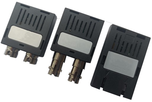
CSFP-B1312-40Dxx 1.25Gb/s CSFP BIDI Transceiver
Product Features
- Two Bi-Directional transceivers in one SFP package
- Up to 1.25Gb/s data links
- Duplex LC connector
- Hot-pluggable SFP footprint
- 1310nm DFB laser transmitter
- RoHS compliant and Lead Free
- Up to 40Km on 9/125um SMF
- Metal enclosure for lower EMI
- Single +3.3V power supply
- Compliant with CSFP MSA 2.0 (Option 2)
- Commercial and industrial operating temperature optional
- SFP MSA SFF-8074i Compliant
- Operating case temperature: Standard 0 to +70°C, Industrial -40 to +85°C
Applications
- Gigabit Ethernet
- Fibre Channel
Regulatory Compliance
- ESD to the Electrical PINs: compatible with MIL-STD-883 Method 3015
- ESD to the Single LC Receptacle: compatible with IEC 61000-4-2
- Immunity compatible with IEC 61000-4-3
- EMI compatible with FCC Part 15 Class B EN55022 Class B (CISPR 22B) VCCI Class B
- Laser Eye Safety compatible with FDA 21CFR 1040.10 and 1040.11 EN60950, EN (IEC) 60825-1,2
- RoHS compliant with RoHS 2 (2011/65/EU)
Absolute Maximum Ratings
| Parameter | Symbol | Min | Max | Unit |
|---|---|---|---|---|
| Supply Voltage | Vcc | -0.5 | 4.5 | V |
| Storage Temperature | Ts | -40 | +85 | °C |
| Operating Humidity | – | 5 | 85 | % |
Recommended Operating Conditions
| Parameter | Parameter | Symbol | Min | Typical | Max | Unit |
|---|---|---|---|---|---|---|
| Operating Case Temperature | Standard | Tc | 0 | +70 | °C | |
| Operating Case Temperature | Industrial | Tc | -40 | +85 | °C | |
| Power Supply Voltage | Power Supply Voltage | Vcc | 3.13 | 3.30 | 3.47 | V |
| Power Supply Current | Power Supply Current | Icc | 500 | mA | ||
| Data Rate | Data Rate | 1.25 | Gbps | |||
| 9/125um G.652 SMF | 9/125um G.652 SMF | Lmax | 40 | km |
Optical and Electrical Characteristics
| Parameter | Symbol | Symbol | Min | Typical | Max | Unit | Notes |
|---|---|---|---|---|---|---|---|
| Transmitter | Transmitter | Transmitter | Transmitter | Transmitter | Transmitter | Transmitter | Transmitter |
| Centre Wavelength | Centre Wavelength | λc | 1260 | 1310 | 1360 | nm | |
| Spectral Width(RMS) | Spectral Width(RMS) | Δλ | – | – | 1 | nm | |
| Side-Mode Suppression Ratio | Side-Mode Suppression Ratio | SMSR | 30 | – | – | dB | |
| Average Output Power | Average Output Power | Pout | -5 | 0 | dBm | 1 | |
| Extinction Ratio | Extinction Ratio | ER | 6.0 | – | – | dB | |
| Optical Rise / Fall Time | Optical Rise / Fall Time | tr / tf | – | – | 260 | ps | 2 |
| Receiver | Receiver | Receiver | Receiver | Receiver | Receiver | Receiver | Receiver |
| Centre Wavelength | Centre Wavelength | λc | 1530 | 1550 | 1570 | nm | |
| Receiver Sensitivity | Receiver Sensitivity | – | – | -24 | dBm | 3, 4 | |
| Receiver Overload | Receiver Overload | -3 | – | – | dBm | ||
| LOS De-Assert | LOS De-Assert | LOSD | -25 | dBm | |||
| LOS Assert | LOS Assert | LOSA | -40 | dBm | |||
| LOS Hysteresis | LOS Hysteresis | – | 0.5 | – | 5 | dB | |
| LOS | LOS | High | 2.0 | Vcc | V | ||
| LOS | LOS | Low | 0.8 | V |
Notes:
1. Class 1 Laser Safety.
2. Unfiltered, 20-80%. Complies with Gigabit Ethernet eye masks when filtered.
3. Measured with conformance signals defined in FC-PI-2 Rev. 10.0 specifications.
4. Measured with PRBS 27-1 at 10-12 BER.
Diagnostics
| Parameter | Range | Unit | Accuracy | Calibration |
|---|---|---|---|---|
| Temperature | 0 to +70 | °C | ±3°C | Internal |
| Temperature | -40 to +85 | °C | ±3°C | Internal |
| Voltage | 2.97 to 3.63 | V | ±3% | Internal |
| Bias Current | 0 to 100 | mA | ±10% | Internal |
| TX Power | -5 to 0 | dBm | ±3dB | Internal |
| RX Power | -24 to -3 | dBm | ±3dB | Internal |
EEPROM Information
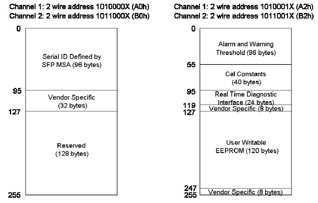
Memory map for 2ch Compact SFP (option 2) is illustrated in below figure. A0h (1010000X) and B0h (1011000X) are the Serial ID addresses for channel 1 and channel 2, respectively. A2h (1010001X) and B2h (1011001X) are the Digital Diagnostic addresses for channel 1 and channel 2.
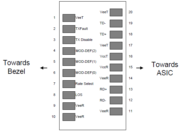
Pin Descriptions
| Pin | Signal Name | Description | Plug Seq. | Notes |
|---|---|---|---|---|
| 1 | VeeT | Transmitter Ground (Common with Receiver Ground) | ||
| 2 | TX Fault | Transmitter Fault. | ||
| 3 | TX1_ Disable | Transmitter Disable of Ch1; Turns off transmitter laser output of Ch1. | ||
| 4 | MOD_DEF(2) | 2-wire Serial Interface Data Line (SDA). | ||
| 5 | MOD_DEF(1) | 2-wire Serial Interface Clock Line (SCL). | ||
| 6 | TD2- | Inverted Transmit Data Input of Ch2. | ||
| 7 | TD2+ | Transmit Data Input of Ch2. | ||
| 8 | LOS1 | Loss of signal for Ch1. | ||
| 9 | RD2+ | Received Data Output of Ch2. | ||
| 10 | RD2- | Inverted Received Data Output of Ch2. | ||
| 11 | VeeT | Transmitter Ground. | ||
| 12 | RD1- | Inverted Received Data Output of Ch1. | ||
| 13 | RD1+ | Received Data Output of Ch1. | ||
| 14 | LOS2 | Loss of signal for Ch2. | ||
| 15 | VccR | Receiver Power Supply. | ||
| 16 | VccT | Transmitter Power Supply. | ||
| 17 | Tx2_Disable | Transmitter Disable of Ch2; Turns off transmitter laser output of Ch2. | ||
| 18 | TD1+ | Transmit Data Input of Ch1. | ||
| 19 | TD1- | Inverted Transmit Data Input of Ch1. | ||
| 20 | VeeT | Transmitter Ground |
Notes:
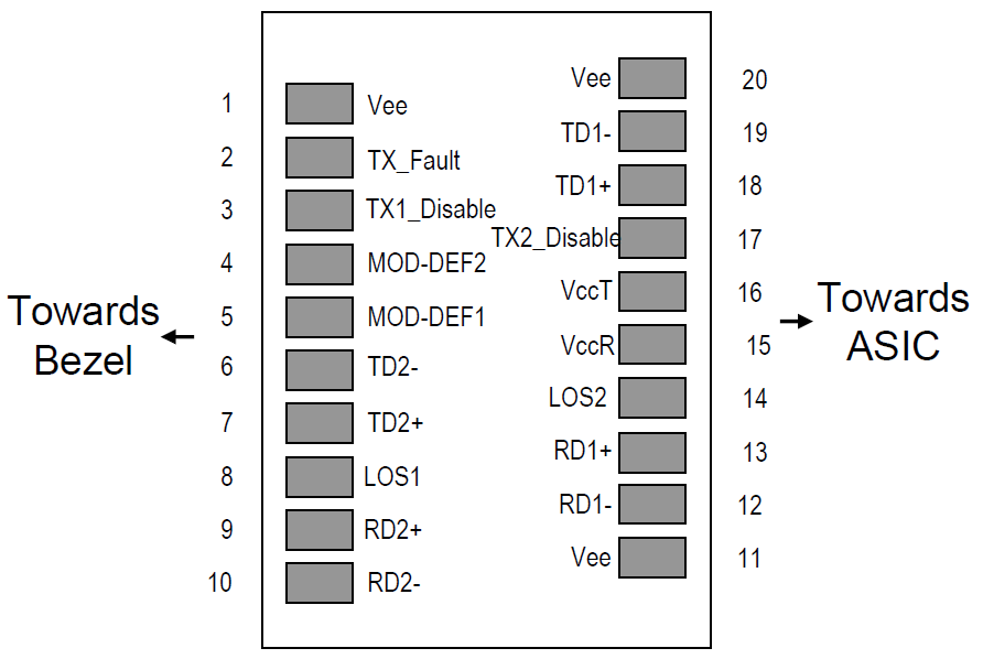
TX_Fault is internally OR output for TX fault conditions in either Channel 1 or Channel 2. In order to determine which channel is at fault, the Host can read the internal memory bits.
Pin-out of Connector Block on Host Board
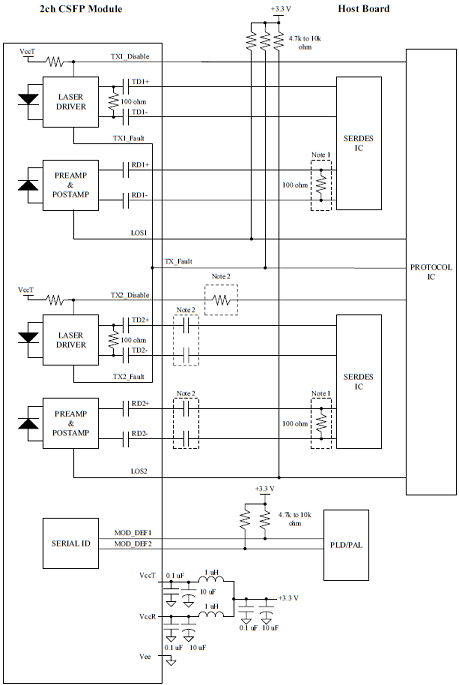
Recommended Interface Circuit
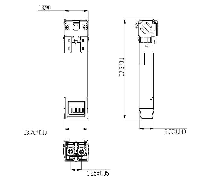
Mechanical Dimensions
Ordering Information
| Part Number | Product Description |
|---|---|
| CSFP-B1312-40D | CSFP Transceiver, BIDI, 1310T/1550R, 1.25Gbps, 40km, with DDM, 0°C~+70°C |
| CSFP-B1312-40DI | CSFP Transceiver, BIDI, 1310T/1550R, 1.25Gbps, 40km, with DDM, -40°C~+85°C |
企业信息
| 项目 | 信息 |
|---|---|
| 公司名 | 北亿纤通 | F-toneNetworks |
| 地区 | 中国四川天府新区 |
| 服务区域 | 全球 |
| 企业电话 | 028-85255257 |
| 企业传真 | 028-85977702 |
| 企业手机 | 19081343401 |
| Site | https://www.f-tone.com |
| 人事部 | hr@f-tone.com |
| 市场部 | sales@f-tone.com |
| 技术支持 | support@f-tone.com |
本产品为CSFP BIDI光收发模块产品线,详细信息,请联系我们的销售人员,谢谢!
Important Notice
Performance figures, data and any illustrative material provided in this data sheet are typical and must be specifically confirmed in writing by F-tone Networks before they become applicable to any particular order or contract. In accordance with the F-tone Networks policy of continuous improvement specifications may change without notice.
The publication of information in this data sheet does not imply freedom from patent or other protective rights of F-tone Networks or others. Further details are available from any F-tone Networks sales representative.