1. 概述 General
FTPC217× 光敏晶体管输出型光耦合器是将红外LED芯片和光敏晶体管芯片封装在一起,以实现电—光—电转换的光电器件。
The FTPC217× Photo-transistor Output Opto-coupler integrates an infrared LED chip and a photo-transistor chip in a single package to achieve electricity-light-electricity conversion.
2. 特点 Features
- 光敏晶体管输出 / Photo-transistor output
- 输入、输出端之间绝缘电压高 / High isolation voltage between input and output: VISO ≥ 3750Vrms
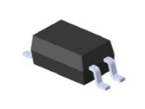
- 贴片式4L塑料封装1.27SOP / Surface mount 4L plastic package 1.27SOP
- 产品符合UL/cUL、VDE、CQC安规认证 / Products comply with UL/cUL, VDE, CQC safety certification
- UL/cUL 证书编号 Certificate No.:E178703
- VDE 证书编号 Certificate No.:40004708
- CQC 证书编号 Certificate No.:CQC23001413664
- 符合RoHS指令最新要求及REACH法规最新要求 / Compliance with the latest requirements of the RoHS Directive and REACH
3. 应用 Applications
- 数字逻辑的传输及变换 / Transmission and conversion of digital logic
- 电源控制及开关 / Power control and switch
- 电路与电路之间、系统与系统之间的电气绝缘隔离与阻抗变换 / Electric insulation and impedance conversion between circuits and systems
4. 极限参数 Absolute Maximum Ratings
Ta = (25±5)℃,RH = 30~75%
| 参数名称 Characteristic | 符号 Symbol | 额定值 Rating | 单位 Unit |
|---|---|---|---|
| 输入端 Input | |||
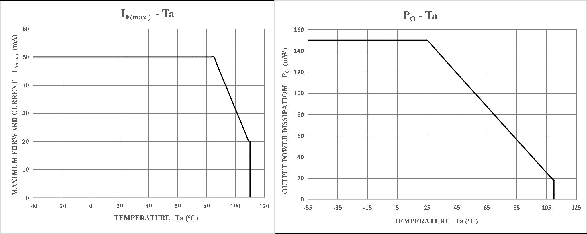
| 正向电流 Forward Current | IF | 50 | mA |
| 正向脉冲电流 Forward Current (Pulsed) Pulse width ≤100μs, frequency 100Hz |
IFP | 1 | A |
| 反向电压 Reverse Voltage | VR | 5 | V |
| 耗散功率 Power Dissipation | PD | 100 | mW |
| 节温 Junction Temperature | TJ | 125 | °C |
| 输出端 Output | |||
| 集电极-发射极击穿电压 Collector-Emitter Breakdown Voltage | V(BR)CEO | 80 | V |
| 发射极-集电极击穿电压 Emitter-Collector Breakdown Voltage | V(BR)ECO | 7 | V |
| 集电极直流电流 Collector Current | IC | 50 | mA |
| 集电极耗散功率 Collector Power Dissipation | PC | 150 | mW |
| 节温 Junction Temperature | TJ | 125 | °C |
| 总计 Total | |||
| 工作温度 Operating Temperature Range | TOPR | -55 ~ +110 | °C |
| 贮存温度 Storage Temperature Range | TSTG | -55 ~ +125 | °C |
| 回流焊接温度 Reflow Soldering (10 seconds) | Th | 260 | °C |
| 总耗散功率 Total Power Dissipation | PT | 200 | mW |
| 输入-输出间绝缘电压 Isolation Voltage (AC, 60s, RH<60%) | VISO | 3750 | Vrms |
5. 光电参数 Opto-Electrical Characteristics
Ta = (25±5)℃,RH = 30~75%
| 参数名称 Characteristic | 符号 Symbol | 测试条件 Conditions | 最小值 Min. | 典型值 Typ. | 最大值 Max. | 单位 Unit |
|---|---|---|---|---|---|---|
| 输入端 Input | ||||||
| 正向电压 Forward Voltage | VF | IF=10mA | 1.2 | 1.4 | V | |
| 反向电流 Reverse Current | IR | VR=6V | 10 | μA | ||
| 输入端子电容 Input Capacitance | CIN | V=0V, f=1MHz | 30 | pF | ||
| 输出端 Output | ||||||
| 集电极-发射极击穿电压 C-E Breakdown Voltage | V(BR)CEO | IC=0.1mA | 80 | V | ||
| 发射极-集电极击穿电压 E-C Breakdown Voltage | V(BR)ECO | IE=0.1mA | 7 | V | ||
| 集电极-发射极泄露电流 C-E Leakage Current | ICEO | VCE=20V | 100 | nA | ||
| 传输隔离特性 Transfer Isolation Features | ||||||
| 直流电流传输比 Current Transfer Ratio | CTR | 见 Table 3 | 具体见表3 See Table 3 | % | ||
| 饱和压降 Saturation Voltage | VCE(sat) | IF=20mA, IC=2mA | 0.4 | V | ||
| 输入-输出间隔电容 Isolation Capacitance | CISO | V=0V, f=1MHz | 0.8 | pF | ||
| 输入-输出间绝缘电阻 Isolation Resistance | RISO | V=500V | 1012 | 1014 | Ω | |
| 输入-输出间绝缘电压 Isolation Voltage (AC, 60s) | VISO | Ioff<0.3mA | 3750 | Vrms | ||
| 开关特性 Switching Characteristics | ||||||
| 脉冲上升时间 Rise Time | tr | VCC=10V, IC=2mA, RL=100Ω |
4 | 18 | μs | |
| 脉冲下降时间 Fall Time | tf | VCC=10V, IC=2mA, RL=100Ω |
7 | 18 | μs | |
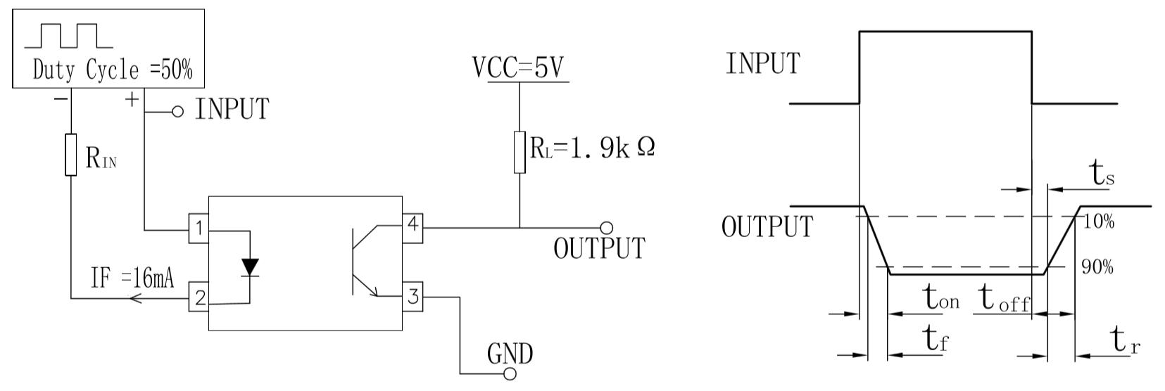
| 开启时间 Turn-on Time | ton | VCC=5V, IF=16mA, RL=1.9kΩ, IC=2mA |
5 | μs | ||
| 存储时间 Storage Time | ts | VCC=5V, IF=16mA, RL=1.9kΩ, IC=2mA |
20 | μs | ||
| 关断时间 Turn-off Time | toff | VCC=5V, IF=16mA, RL=1.9kΩ, IC=2mA |
60 | μs | ||
表3 CTR分档表 Binning Table of CTR
测试条件 Test Condition: IF=5mA, VCE=5V
| 代码 Code | 最小值 Min. (%) | 最大值 Max. (%) |
|---|---|---|
| A | 80 | 160 |
| B | 130 | 260 |
| C | 200 | 400 |
| D | 300 | 600 |
| L | 100 | 300 |
| L1 | 100 | 400 |
| S | 130 | 300 |
CTR代码说明:FTPC217× 中 “×” 为CTR代码,具体见上表。
CTR Code: The “×” in FTPC217× represents the CTR code as shown in the table above.
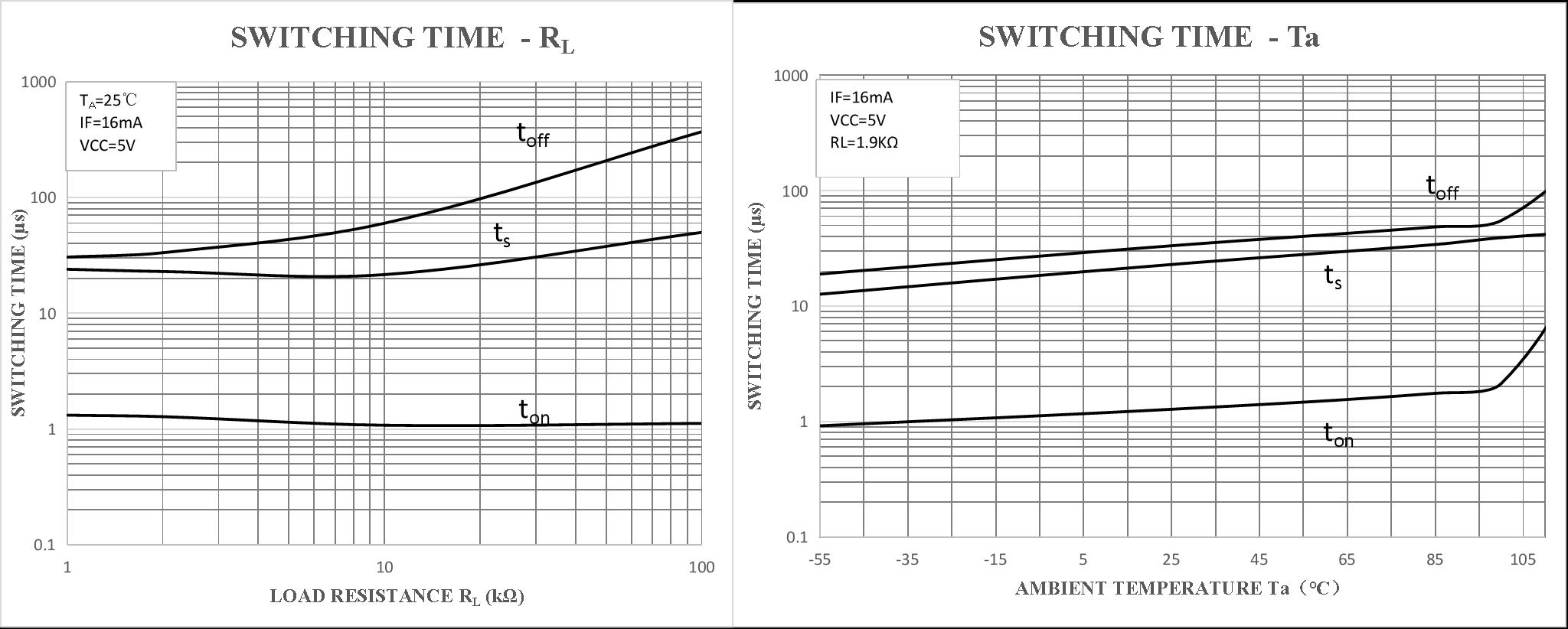
6. 特性曲线 Characteristic Curves
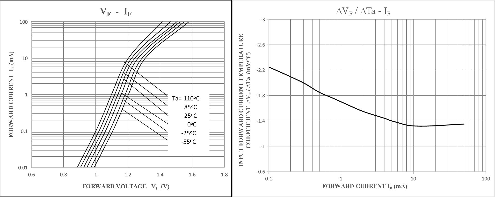
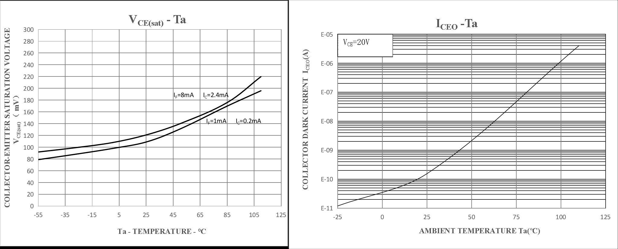
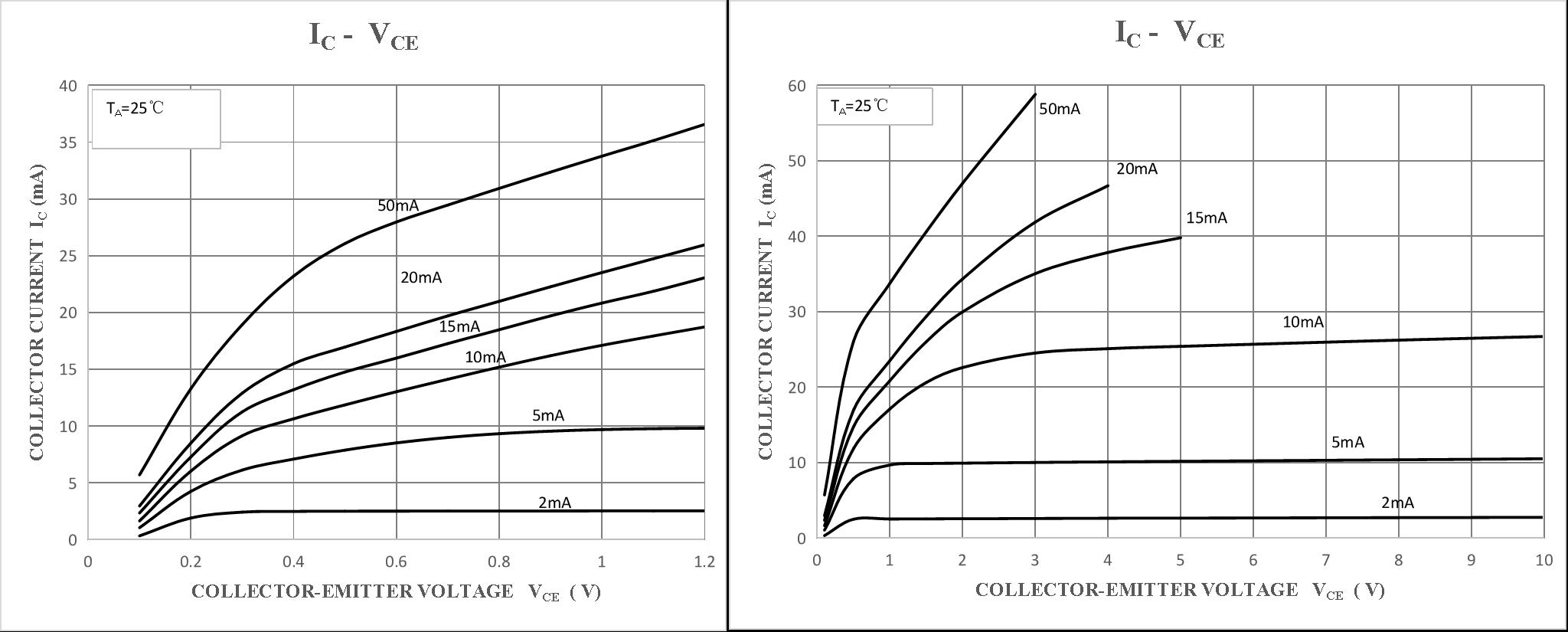
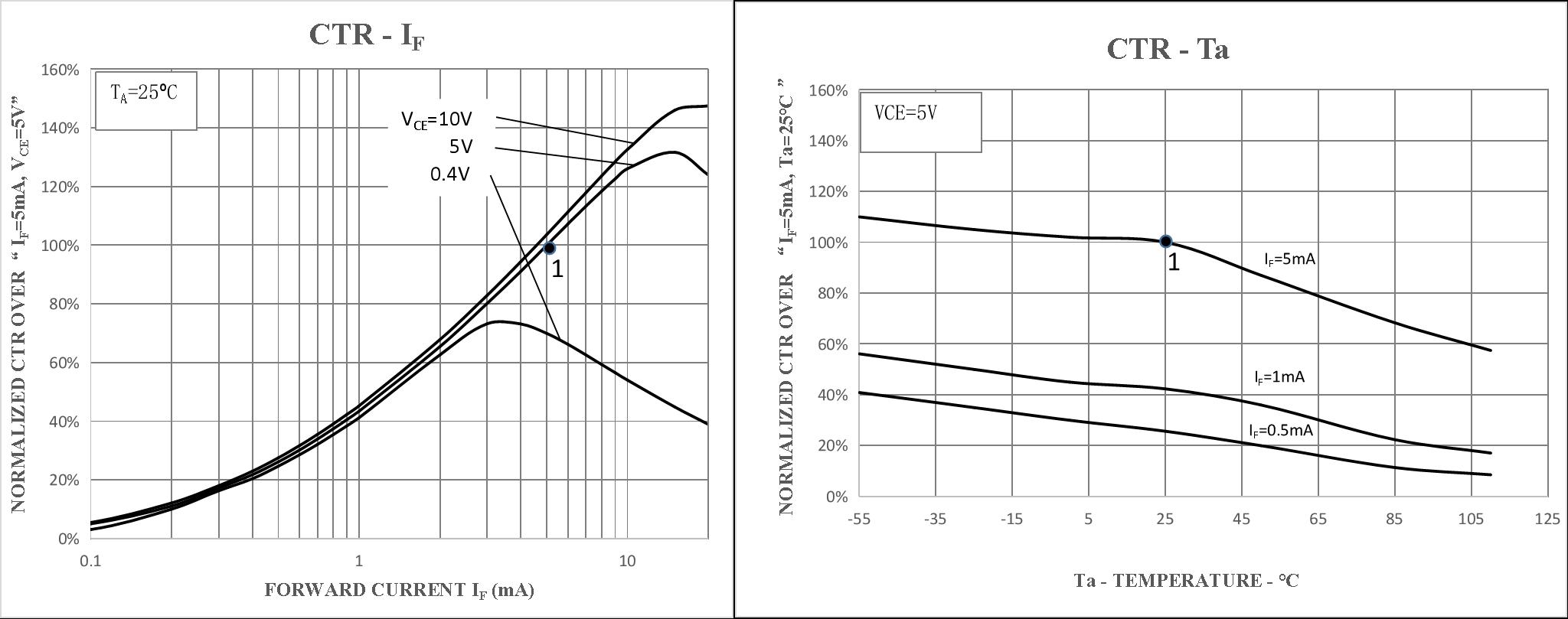
7. 电原理图 Schematic Diagram
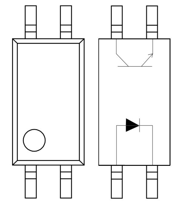
FTPC217× 内部由红外LED和光敏晶体管组成,实现输入与输出之间的电气隔离。
The FTPC217× internally consists of an infrared LED and a photo-transistor, providing electrical isolation between input and output.
8. 外形尺寸 Dimensions
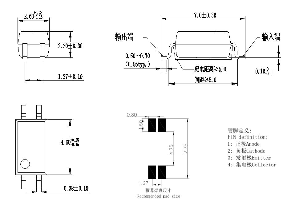
封装形式:1.27mm间距SOP-4L塑料封装
Package: 1.27mm pitch SOP-4L plastic package
9. 标志 Marking
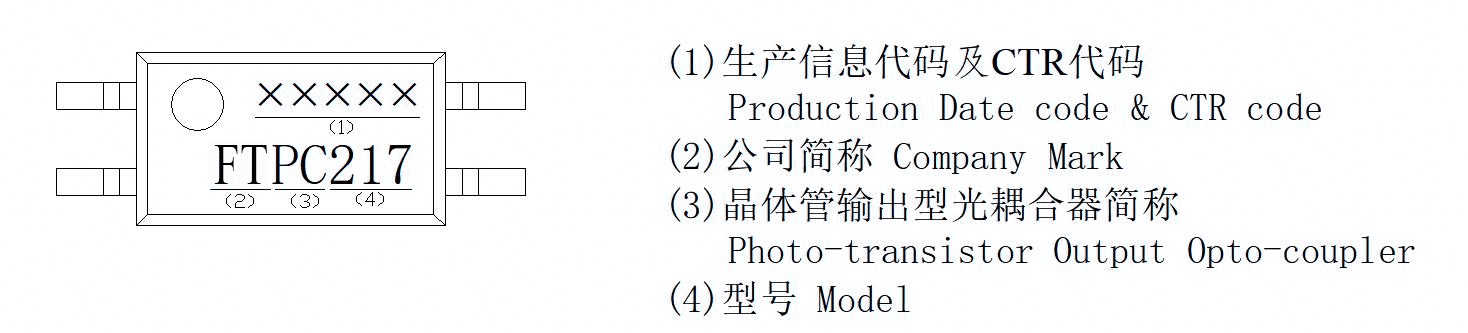
10. 包装方式 Packing
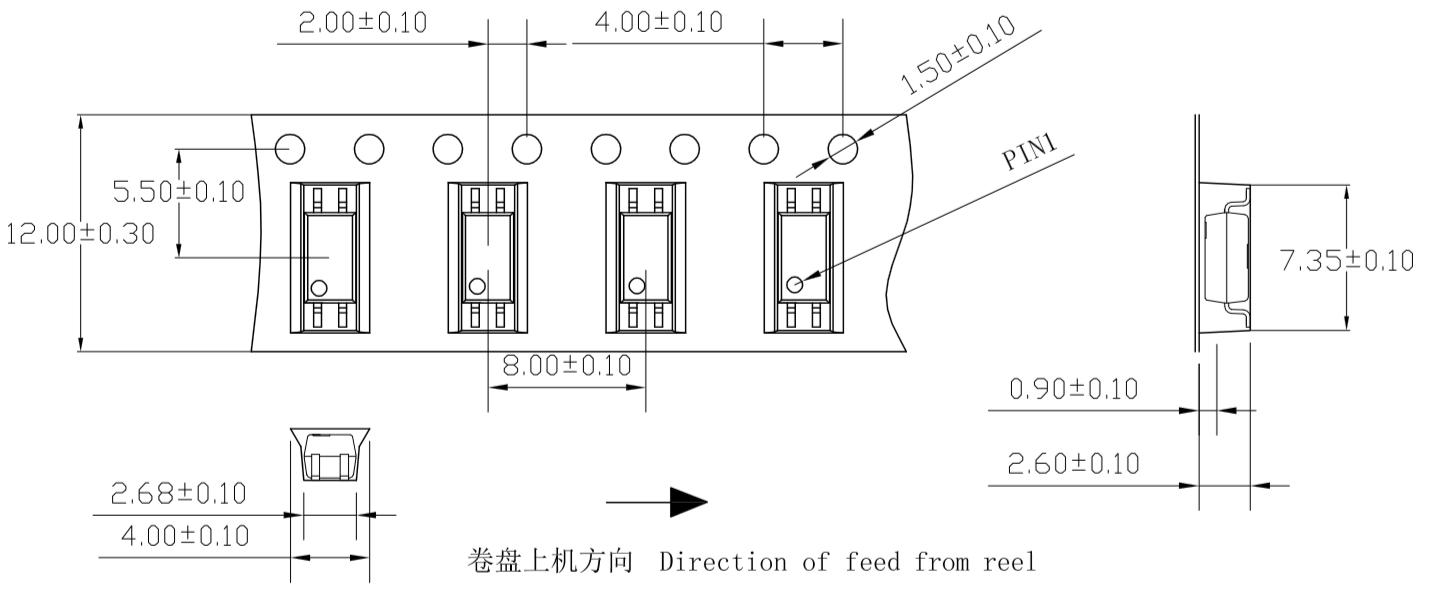
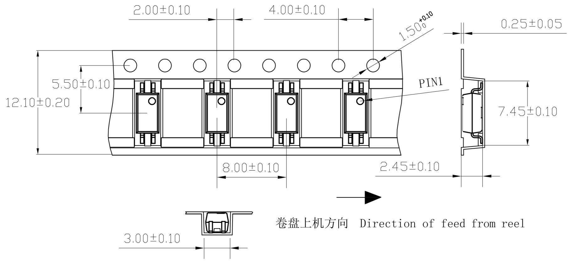
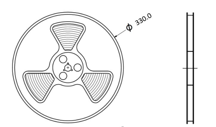
10.1 编带包装 Tape and Reel
适用于FTPC217×系列。For FTPC217× series.
- 每卷数量 Qty/reel:3000 pcs
- 每箱数量 Qty/ctn:45000 pcs
- 内包装:每卷盘3000只,贴合格证(型号、生产日期代号、检验员代号)
- 外包装:公司名称、地址、商标、产品型号、数量等标志
11. 使用注意事项 Note
- 推荐贮存温度 Recommend storage Temp.:0~40°C
- 推荐贮存湿度 Recommend storage humidity:<60%
- 湿气敏感度等级 Moisture Sensitivity Level:MSL 1
- 静电防护等级 ESD (HBM):≥2kV
- 引脚镀锡厚度 Thickness of Sn plated on lead frame:≥5μm
11.1 推荐焊接条件 Recommended Soldering Conditions
- 请勿使用超过最高贮存温度的物体直接接触环氧本体。
Do not contact the epoxy body directly with objects exceeding the maximum storage temperature. - 在高温下不要对环氧本体施加压力,特殊情况下施加的力不应超过2.5N。
Do not apply pressure to the epoxy at high temperatures; in special cases, force should not exceed 2.5N.
回流焊 Reflow Soldering
| 项目 Items | 条件 Conditions |
|---|---|
| 预热 Preheat – Temperature Min (TSmin) | 150°C |
| 预热 Preheat – Temperature Max (TSmax) | 200°C |
| 预热时间 Preheat Time (ts) | 90±30 sec |
| 焊接区温度 Soldering Zone Temperature (TL) | 217°C |
| 焊接区时间 Soldering Zone Time (tL) | 60 ~ 100 sec |
| 最高温度 Peak Temperature (TP) | 250°C |
| 升温速率 Ramp-up rate | 3°C/sec max. |
| 降温速率 Ramp-down rate | 3~6°C/sec |
推荐锡膏规格:熔点217℃,组分SnAg3Cu0.5
Recommend tin glue: melting temperature 217°C, contains SnAg3Cu0.5
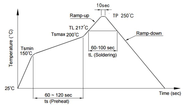
注意:建议在所示温度和时间条件下进行一次回流焊,最多不能超过三次。
Note: One time soldering reflow is recommended. Do not solder more than three times.
手工烙铁焊 Manual Soldering
- 手工烙铁焊仅用于产品返修或样品测试。
Manual soldering is only applicable to product repair or sample testing. - 温度 Temperature:360°C ± 5°C
- 时间 Time:≤ 3s
- 返修次数 Repair times:≤ 2次
订购信息 Ordering Information
| 型号 Model | CTR分档 CTR Rank | 包装方式 Packing |
|---|---|---|
| FTPC217A | A (80~160%) | Tube / Tape & Reel |
| FTPC217B | B (130~260%) | Tube / Tape & Reel |
| FTPC217C | C (200~400%) | Tube / Tape & Reel |
| FTPC217D | D (300~600%) | Tube / Tape & Reel |
| FTPC217L | L (100~300%) | Tube / Tape & Reel |
| FTPC217L1 | L1 (100~400%) | Tube / Tape & Reel |
| FTPC217S | S (130~300%) | Tube / Tape & Reel |
注:型号后缀 -(R) 表示编带包装(Tape & Reel)。
Note: Suffix -(R) indicates Tape & Reel packing.
本产品为【光耦合器/Optocoupler】产品线,详细信息,请联系我们的销售人员,谢谢!
Important Notice
Performance figures, data and any illustrative material provided in this data sheet are typical and must be specifically confirmed in writing by F-tone Networks before they become applicable to any particular order or contract. In accordance with the F-tone Networks policy of continuous improvement specifications may change without notice. The publication of information in this data sheet does not imply freedom from patent or other protective rights of F-tone Networks or others. Further details are available from any F-tone Networks sales representative.