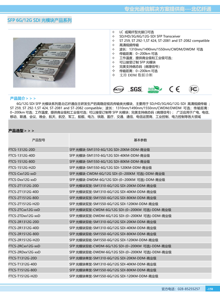
Product Features
- Up to 1.25Gb/s data links
- 1310nm FP laser transmitter and PIN photo-detector
- Up to 10km on 9/125µm SMF
- Hot-pluggable SFP footprint
- Duplex LC/UPC type pluggable optical interface
- Low power dissipation
- Metal enclosure, for lower EMI
- RoHS compliant and lead-free
- Single +3.3V power supply
- Support Digital Diagnostic Monitoring interface
- Compliant with SFF-8472
- Meet ESD requirements, resist 8KV direct contact voltage
- Case operating temperature: Commercial 0°C~+70°C / Extended -10°C~+80°C / Industrial -40°C~+85°C
Applications
- Switch to Switch Interface
- Gigabit Ethernet
- 1x Fiber channel Application
- Switched Backplane Applications
- Router/Server Interface
- Other Optical Links
Product Description
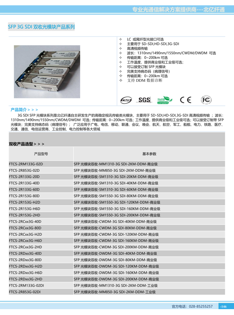
F-tone’s FTCS-1312-10Dxx Small Form Factor Pluggable (SFP) transceivers are compatible with the Small Form Factor Pluggable Multi-Sourcing Agreement (MSA). The transceiver consists of five sections: the LD driver, the limiting amplifier, the digital diagnostic monitor, the FP laser and the PIN photo-detector. The module data link up to 10KM in 9/125um single mode fiber.
The optical output can be disabled by a TTL logic high-level input of Tx Disable, and the system also can disable the module via I2C. Tx Fault is provided to indicate that degradation of the laser. Loss of signal (LOS) output is provided to indicate the loss of an input optical signal of receiver or the link status with partner. The system can also get the LOS (or Link)/Disable/Fault information via I2C register access.
Part Number Ordering Information
| Part Number | Data Rate (Mbps) | Media | Wavelength (nm) | Distance (km) | Temp. Range (℃) | Type |
|---|---|---|---|---|---|---|
| FTCS-1312-10D | 1250 | Single mode fiber | 1310 | 10 | 0~70 | Commercial |
| FTCS-1312-10DE | 1250 | Single mode fiber | 1310 | 10 | -10~80 | Extended |
| FTCS-1312-10DI | 1250 | Single mode fiber | 1310 | 10 | -40~85 | Industrial |
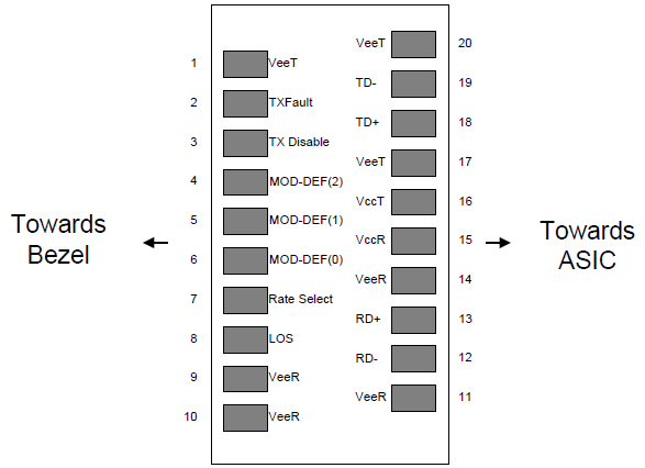
Pin Definitions and Pin Diagram
| Pin | Symbol | Name/Description | NOTE |
|---|---|---|---|
| 1 | VEET | Transmitter Ground (Common with Receiver Ground) | 1 |
| 2 | TFAULT | Transmitter Fault. | |
| 3 | TDIS | Transmitter Disable. Laser output disabled on high or open. | 2 |
| 4 | MOD_DEF (2) | Module Definition 2. Data line for Serial ID. | 3 |
| 5 | MOD_DEF (1) | Module Definition 1. Clock line for Serial ID. | 3 |
| 6 | MOD_DEF (0) | Module Definition 0. Grounded within the module. | 3 |
| 7 | Rate Select | No connection required | 4 |
| 8 | LOS | Loss of Signal indication. Logic 0 indicates normal operation. | 5 |
| 9 | VEER | Receiver Ground (Common with Transmitter Ground) | 1 |
| 10 | VEER | Receiver Ground (Common with Transmitter Ground) | 1 |
| 11 | VEER | Receiver Ground (Common with Transmitter Ground) | 1 |
| 12 | RD- | Receiver Inverted DATA out. AC Coupled | |
| 13 | RD+ | Receiver Non-inverted DATA out. AC Coupled | |
| 14 | VEER | Receiver Ground (Common with Transmitter Ground) | 1 |
| 15 | VCCR | Receiver Power Supply | |
| 16 | VCCT | Transmitter Power Supply | |
| 17 | VEET | Transmitter Ground (Common with Receiver Ground) | 1 |
| 18 | TD+ | Transmitter Non-Inverted DATA in. AC Coupled. | |
| 19 | TD- | Transmitter Inverted DATA in. AC Coupled. | |
| 20 | VEET | Transmitter Ground (Common with Receiver Ground) | 1 |
Notes:
- Circuit ground is internally isolated from chassis ground.
- Laser output disabled on TDIS >2.0V or open, enabled on TDIS <0.8V.
- Should be pulled up with 4.7k – 10kohms on host board to a voltage between 2.0V and 3.6V. MOD_DEF(0) pulls line low to indicate module is plugged in.
- Optional input used to control the receiver bandwidth for compatibility with multiple data rates. Low (0–0.8V): Reduced Bandwidth; High (2.0–3.465V): Full Bandwidth.
- LOS is open collector output should be pulled up with 4.7k – 10kohms. Logic 0 indicates normal operation; logic 1 indicates loss of signal.
Absolute Maximum Ratings
| Parameter | Symbol | Min. | Typ. | Max. | Unit | Note |
|---|---|---|---|---|---|---|
| Storage Temperature | Ts | -40 | 85 | ºC | ||
| Relative Humidity | RH | 5 | 95 | % | ||
| Power Supply Voltage | VCC | -0.5 | 4 | V | ||
| Signal Input Voltage | -0.3 | Vcc+0.3 | V | |||
| Receiver Damage Threshold | +5 | dBm |
Recommended Operating Conditions
| Parameter | Symbol | Min. | Typ. | Max. | Unit | Note |
|---|---|---|---|---|---|---|
| Case Operating Temperature | Tcase | 0 | 70 | ºC | FTCS-1312-10D | |
| Case Operating Temperature | Tcase | -10 | 80 | ºC | FTCS-1312-10DE | |
| Case Operating Temperature | Tcase | -40 | 85 | ºC | FTCS-1312-10DI | |
| Power Supply Voltage | VCC | 3.13 | 3.3 | 3.47 | V | |
| Power Supply Current | ICC | 250 | mA | |||
| Power Supply Noise Rejection | 100 | mVp-p | 100Hz to 1MHz | |||
| Data Rate | 1250/1250 | Mbps | TX Rate/RX Rate | |||
| Transmission Distance | 10 | KM | ||||
| Coupled Fiber | Single mode fiber | 9/125um SMF |
Specification of Transmitter
| Parameter | Symbol | Min. | Typ. | Max. | Unit | Note |
|---|---|---|---|---|---|---|
| Average Output Power | POUT | -9 | -3 | dBm | Note (1) | |
| Extinction Ratio | ER | 9 | dB | |||
| Center Wavelength | λC | 1270 | 1310 | 1360 | nm | |
| Side Mode Suppression Ratio | SMSR | – | dB | |||
| Spectrum Bandwidth (RMS) | σ | 3.5 | nm | |||
| Transmitter OFF Output Power | POff | -45 | dBm | |||
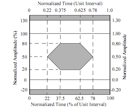
| Output Eye Mask | Compliant with IEEE802.3 z | Note (2) |
Notes: (1) Measure at 2^7-1 NRZ PRBS pattern. (2) Transmitter eye mask definition.
Specification of Receiver
| Parameter | Symbol | Min. | Typ. | Max. | Unit | Note |
|---|---|---|---|---|---|---|
| Input Optical Wavelength | λIN | 1270 | 1610 | nm | PIN-TIA | |
| Receiver Sensitivity | PIN | -20 | dBm | Note (1) | ||
| Input Saturation Power (Overload) | PSAT | -3 | dBm | |||
| Loss Of Signal Assert | PA | -36 | dBm | |||
| Loss Of Signal De-assert | PD | -21 | dBm | Note (2) | ||
| LOS Hysteresis | PA-PD | 0.5 | 2 | 6 | dB |
Notes: (1) Measured with Light source 1310nm, ER=9dB; BER ≤10⁻¹² @PRBS=2⁷⁻¹ NRZ. (2) When LOS de-asserted, the RX data± output is High-level (fixed).
Electrical Interface Characteristics
| Parameter | Symbol | Min. | Typ. | Max. | Unit | Note |
|---|---|---|---|---|---|---|
| Power Consumption | P | 0.85 | W | |||
| Supply Current | Icc | 250 | mA | |||
| Single-ended Input Voltage Tolerance | VCC | -0.3 | 4.0 | V | Transmitter | |
| Differential Input Voltage Swing | Vin,pp | 100 | 800 | mVpp | Transmitter | |
| Differential Input Impedance | Zin | 90 | 100 | 110 | Ohm | Transmitter |
| Transmit Disable Assert Time | 5 | us | Transmitter | |||
| Transmit Disable Voltage | Vdis | Vcc-1.3 | Vcc | V | Transmitter | |
| Transmit Enable Voltage | Ven | Vee-0.3 | 0.8 | V | Transmitter | |
| Differential Output Voltage Swing | Vout,pp | 500 | 900 | mVpp | Receiver | |
| Differential Output Impedance | Zout | 90 | 100 | 110 | Ohm | Receiver |
| Data output rise/fall time | Tr/Tf | 100 | ps | 20% to 80% | ||
| LOS Assert Voltage | VlosH | Vcc-1.3 | Vcc | V | ||
| LOS De-assert Voltage | VlosL | Vee-0.3 | 0.8 | V |
Digital Diagnostic Functions
F-tone’s FTCS-1312-10Dxx transceivers support the 2-wire serial communication protocol as defined in the SFP MSA. The standard SFP serial ID provides access to identification information that describes the transceiver’s capabilities, standard interfaces, manufacturer, and other information.
Additionally, F-tone’s SFP transceivers provide a unique enhanced digital diagnostic monitoring interface, which allows real-time access to device operating parameters such as transceiver temperature, laser bias current, transmitted optical power, received optical power and transceiver supply voltage. It also defines a sophisticated system of alarm and warning flags, which alerts end-users when particular operating parameters are outside of a factory set normal range.
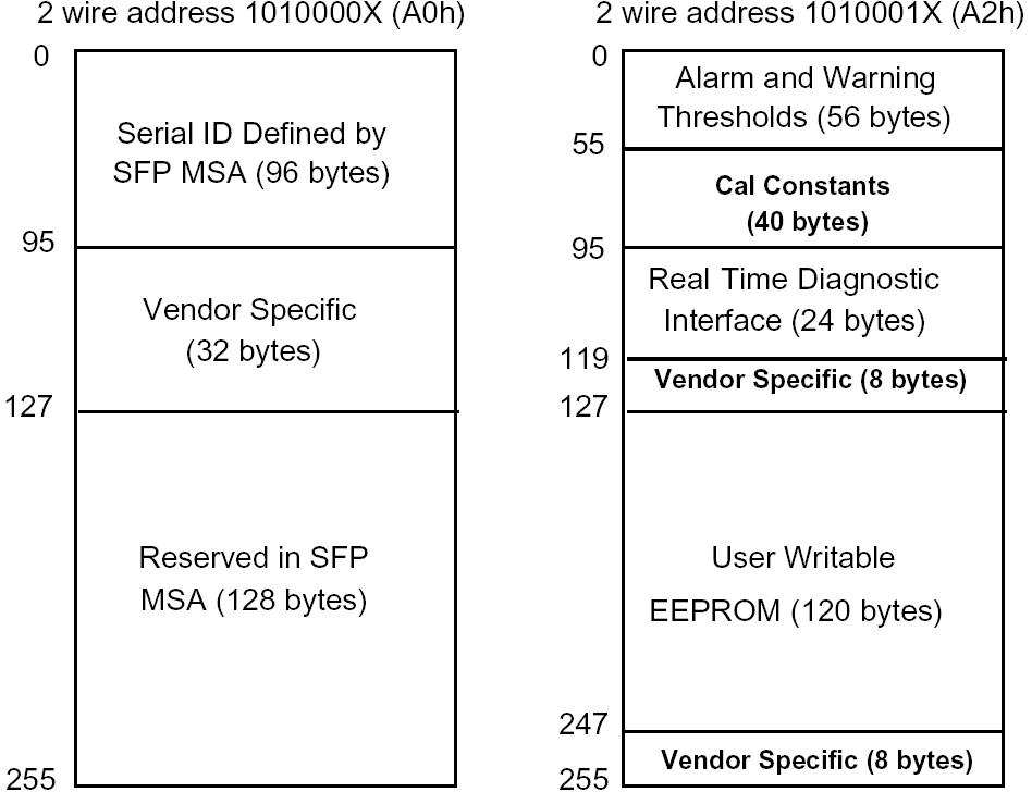
The SFP MSA defines a 256-byte memory map in E2PROM that is accessible over a 2-wire serial interface at the 8 bit address 1010000X (A0h). The digital diagnostic monitoring interface makes use of the 8 bit address 1010001X (A2h). The digital diagnostics for the FTCS-1312-10Dxx are internally calibrated by default.
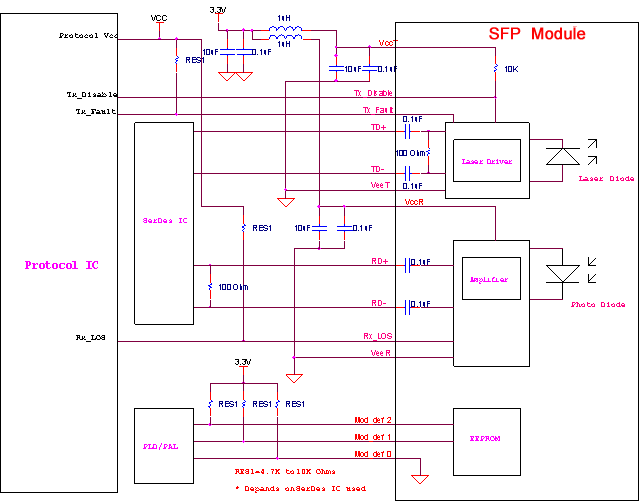
Recommend Circuit Schematic
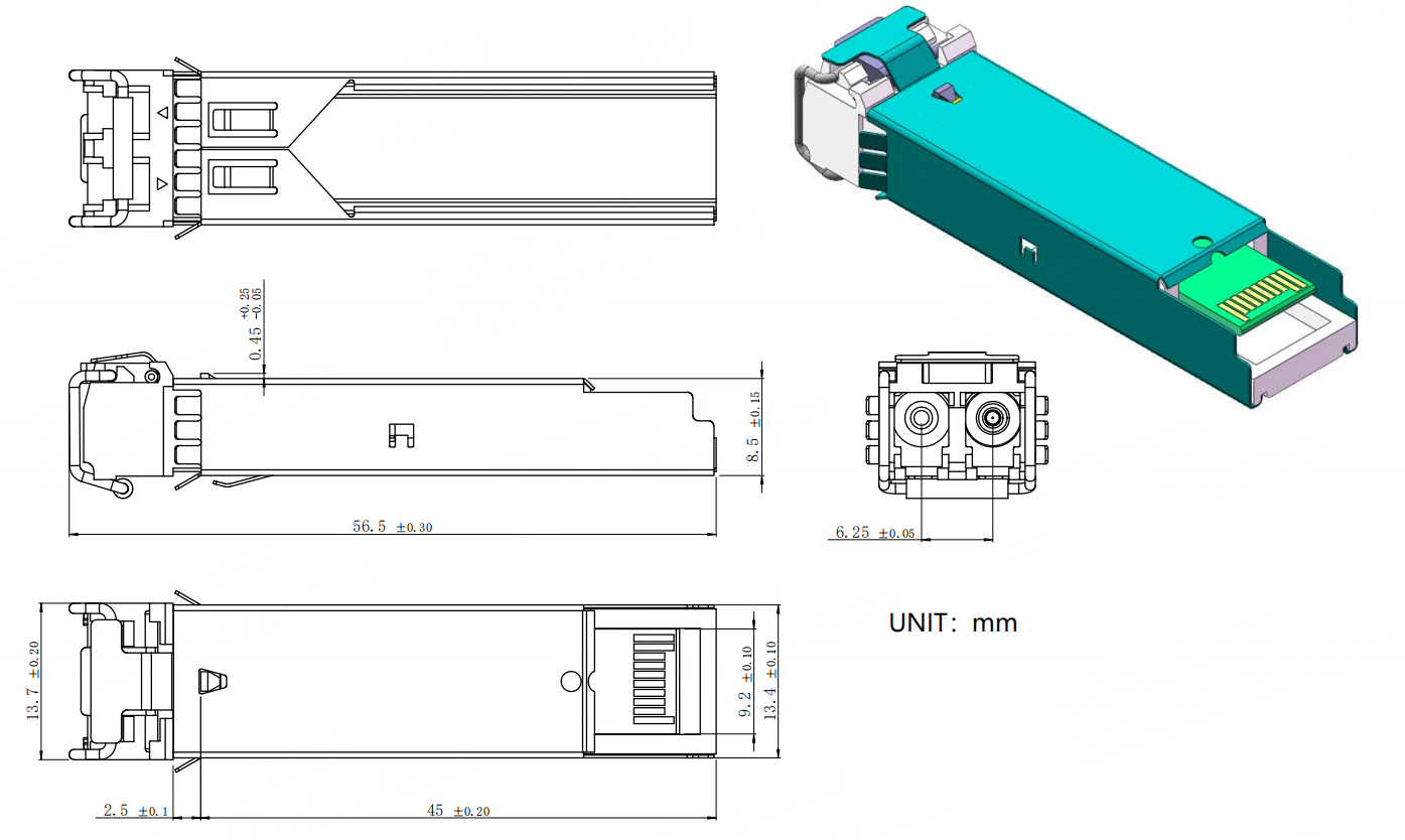
Mechanical Specifications (Unit: mm)
Regulatory Compliance
| Feature | Reference | Performance |
|---|---|---|
| Electrostatic discharge (ESD) | IEC/EN 61000-4-2 | Compatible with standards |
| Electromagnetic Interference (EMI) | FCC Part 15 Class B / EN 55022 Class B (CISPR 22A) | Compatible with standards |
| Laser Eye Safety | FDA 21CFR 1040.10, 1040.11 / IEC/EN 60825-1, 2 | Class 1 laser product |
| Component Recognition | IEC/EN 60950, UL | Compatible with standards |
| ROHS | 2002/95/EC | Compatible with standards |
| EMC | EN61000-3 | Compatible with standards |
Ordering Information
| Part Number | Product Description |
|---|---|
| FTCS-1312-10D | SFP Transceiver, 1310nm, 1.25Gbps, 10km, with DDM, 0°C~+70°C |
| FTCS-1312-10DE | SFP Transceiver, 1310nm, 1.25Gbps, 10km, with DDM, -10°C~+80°C |
| FTCS-1312-10DI | SFP Transceiver, 1310nm, 1.25Gbps, 10km, with DDM, -40°C~+85°C |
Important Notice
本产品为【1.25G SFP 单模光模块】产品线,详细信息,请联系我们的销售人员,谢谢!
Performance figures, data and any illustrative material provided in this data sheet are typical and must be specifically confirmed in writing by F-tone Networks before they become applicable to any particular order or contract. In accordance with the F-tone Networks policy of continuous improvement specifications may change without notice.
The publication of information in this data sheet does not imply freedom from patent or other protective rights of F-tone Networks or others. Further details are available from any F-tone Networks sales representative.