1.25Gbps SFP Transceiver, Single Mode, 10km Reach — FTCS-1312-10DIWN
The FTCS-1312-10DIWN is a high-performance, cost-effective SFP transceiver module supporting data rate of 1.25Gbps and 10km transmission distance over single-mode fiber (SMF). It features a 1310nm FP laser transmitter and PIN photodiode integrated with a trans-impedance preamplifier (TIA) and MCU control unit, compliant with SFP MSA and SFF-8472 digital diagnostics with duplex LC receptacle.
Product Features
- Supports up to 1.25Gbps bit rates
- Hot-pluggable SFP footprint
- 1310nm FP laser and PIN photo detector, up to 10km for SMF transmission
- Compliant with SFP MSA and SFF-8472 with duplex LC receptacle
- Compatible with RoHS
- Single +3.3V power supply
- Real Time Digital Diagnostic Monitoring (DDM)
- Operating case temperature: Standard 0~+70°C / Extended -20~+80°C / Industrial -40~+85°C
Applications
- 1.25Gbps Optical systems
- Gigabit Ethernet
- 1.063Gbps Fiber Channel
- Other Optical links
Product Description
The SFP transceivers are high performance, cost effective modules supporting data rate of 1.25Gbps and 10km transmission distance with SMF. The transceiver consists of three sections: a FP laser transmitter, a PIN photodiode integrated with a trans-impedance preamplifier (TIA) and MCU control unit. All modules satisfy class I laser safety requirements. The transceivers are compatible with SFP Multi-Source Agreement and SFF-8472 digital diagnostics functions.
Transceiver Functional Diagram
Absolute Maximum Ratings
| Parameter | Symbol | Min | Max | Unit |
|---|---|---|---|---|
| Supply Voltage | Vcc | -0.5 | 4.5 | V |
| Storage Temperature | Ts | -40 | +85 | °C |
| Operating Humidity | – | 5 | 85 | % |
Recommended Operating Conditions
| Parameter | Symbol | Min | Typical | Max | Unit |
|---|---|---|---|---|---|
| Operating Case Temperature (Standard) | Tc | 0 | – | +70 | °C |
| Operating Case Temperature (Extended) | Tc | -20 | – | +80 | °C |
| Operating Case Temperature (Industrial) | Tc | -40 | – | +85 | °C |
| Power Supply Voltage | Vcc | 3.135 | 3.30 | 3.465 | V |
| Power Supply Current | Icc | – | – | 300 | mA |
| Data Rate | – | 0.1 | 1.25 | – | Gbps |
Optical and Electrical Characteristics
Transmitter Characteristics (TA = Tcase operating)
| Parameter | Symbol | Min | Typ | Max | Unit | Notes |
|---|---|---|---|---|---|---|
| Centre Wavelength | λc | 1260 | 1310 | 1360 | nm | – |
| Spectral Width (RMS) | Δλ | – | – | 3 | nm | – |
| Side-Mode Suppression Ratio | SMSR | – | – | – | dB | – |
| Average Output Power | Pout | -9 | – | 0 | dBm | 1 |
| Extinction Ratio | ER | 9.0 | – | – | dB | – |
| Data Input Swing Differential | VIN | 180 | – | 1200 | mV | 2 |
| Input Differential Impedance | ZIN | 90 | 100 | 110 | Ω | – |
| TX Disable | – | 2.0 | – | Vcc | V | – |
| TX Enable | – | 0 | – | 0.8 | V | – |
| TX Fault | – | 2.0 | – | Vcc | V | – |
| TX Normal | – | 0 | – | 0.8 | V | – |
Receiver Characteristics (TA = Tcase operating)
| Parameter | Symbol | Min | Typ | Max | Unit | Notes |
|---|---|---|---|---|---|---|
| Centre Wavelength | λc | 1260 | – | 1610 | nm | – |
| Receiver Sensitivity | – | – | – | -23 | dBm | 3 |
| Receiver Overload | – | -1 | – | – | dBm | 3 |
| LOS De-Assert | LOSD | – | – | -24 | dBm | – |
| LOS Assert | LOSA | -38 | – | – | dBm | – |
| LOS Hysteresis | – | 0.5 | – | 4 | dB | – |
| Data Output Swing Differential | Vout | 600 | 800 | 1000 | mV | 4 |
| LOS High | – | 2.0 | – | Vcc | V | – |
| LOS Low | – | – | – | 0.8 | V | – |
Notes:
1. The optical power is launched into SMF.
2. PECL input, internally AC-coupled and terminated.
3. Measured with a PRBS 27-1 test pattern @1250Mbps, BER ≤1×10-12.
4. Internally AC-coupled.
Timing Parameters
| Parameter | Symbol | Min | Typ | Max | Unit |
|---|---|---|---|---|---|
| Tx Disable Negate Time | t_on | – | – | 1 | ms |
| Tx Disable Assert Time | t_off | – | – | 10 | µs |
| Time To Initialize (incl. Reset of Tx Fault) | t_init | – | – | 300 | ms |
| Tx Fault Assert Time | t_fault | – | – | 100 | µs |
| Tx Disable To Reset | t_reset | 10 | – | – | µs |
| LOS Assert Time | t_loss_on | – | – | 100 | µs |
| LOS De-assert Time | t_loss_off | – | – | 100 | µs |
| Serial ID Clock Rate | f_serial_clock | – | 100 | 400 | KHz |
| MOD_DEF (0:2)-High | VH | 2 | – | Vcc | V |
| MOD_DEF (0:2)-Low | VL | – | – | 0.8 | V |
Digital Diagnostic
The transceivers provide serial ID memory contents and diagnostic information about the present operating conditions by the 2-wire serial interface (SCL, SDA). The diagnostic information with internal calibration or external calibration all are implemented, including received power monitoring, transmitted power monitoring, bias current monitoring, supply voltage monitoring and temperature monitoring.
| Parameter | Range | Unit | Accuracy | Calibration |
|---|---|---|---|---|
| Temperature (Standard) | 0 to +70 | °C | ±3°C | Internal |
| Temperature (Extended) | -20 to +80 | °C | ±3°C | Internal |
| Temperature (Industrial) | -40 to +85 | °C | ±3°C | Internal |
| Voltage | 3.0 to 3.6 | V | ±3% | Internal |
| Bias Current | 0 to 100 | mA | ±10% | Internal |
| TX Power | -9 to 0 | dBm | ±3dB | Internal |
| RX Power | -23 to -1 | dBm | ±3dB | Internal |
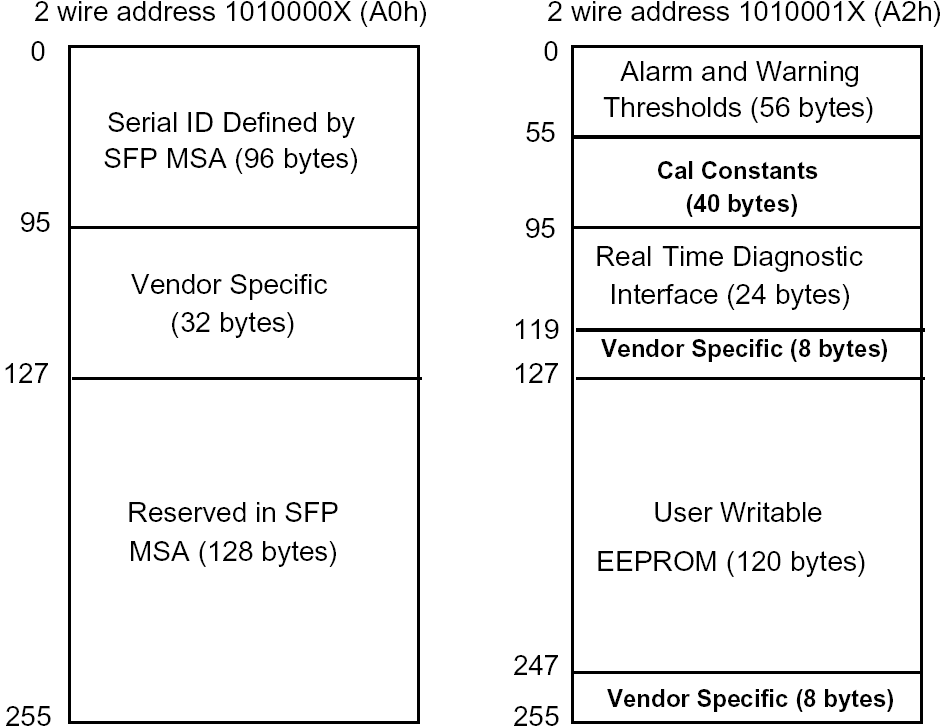
Digital Diagnostic Memory Map
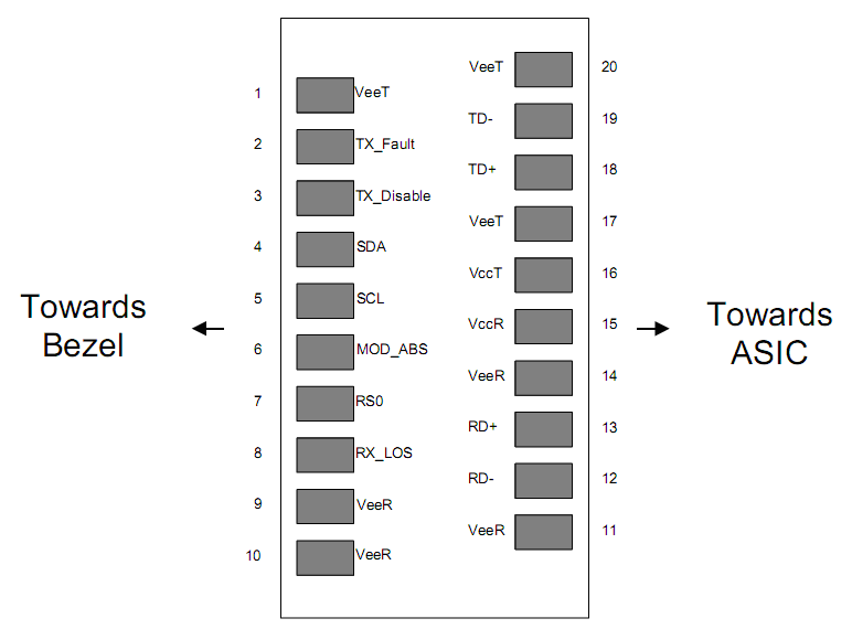
Pin Descriptions (20-Pin SFP)
| Pin | Signal Name | Description | Plug Seq. | Notes |
|---|---|---|---|---|
| 1 | VEET | Transmitter Ground | 1 | |
| 2 | TX FAULT | Transmitter Fault Indication | 3 | 1 |
| 3 | TX DISABLE | Transmitter Disable | 3 | 2 |
| 4 | SDA | SDA Serial Data Signal | 3 | |
| 5 | SCL | SCL Serial Clock Signal | 3 | |
| 6 | MOD_ABS | Module Absent | 3 | |
| 7 | RS0 | Not Connected | 3 | |
| 8 | LOS | Loss of Signal | 3 | 3 |
| 9 | VEER | Receiver Ground | 1 | |
| 10 | VEER | Receiver Ground | 1 | |
| 11 | VEER | Receiver Ground | 1 | |
| 12 | RD- | Inv. Received Data Out | 3 | 4 |
| 13 | RD+ | Received Data Out | 3 | 4 |
| 14 | VEER | Receiver Ground | 1 | |
| 15 | VCCR | Receiver Power Supply | 2 | |
| 16 | VCCT | Transmitter Power Supply | 2 | |
| 17 | VEET | Transmitter Ground | 1 | |
| 18 | TD+ | Transmit Data In | 3 | 5 |
| 19 | TD- | Inv. Transmit Data In | 3 | 5 |
| 20 | VEET | Transmitter Ground | 1 |
Pin Notes:
1) TX Fault is an open collector output, pulled up with 4.7k~10kΩ on host board to 2.0V~Vcc+0.3V. Logic 0=normal; Logic 1=laser fault.
2) Laser output disabled on TDIS >2.0V or open; enabled on TDIS <0.8V.
3) LOS is open collector output, pulled up with 4.7k~10kΩ to 2.0V~3.6V.
4) RD-/+: Internally AC-coupled 100Ω differential receiver outputs.
5) TD-/+: Internally AC-coupled differential transmitter inputs with 100Ω termination.
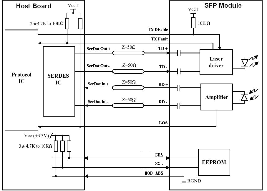
Recommended Interface Circuit
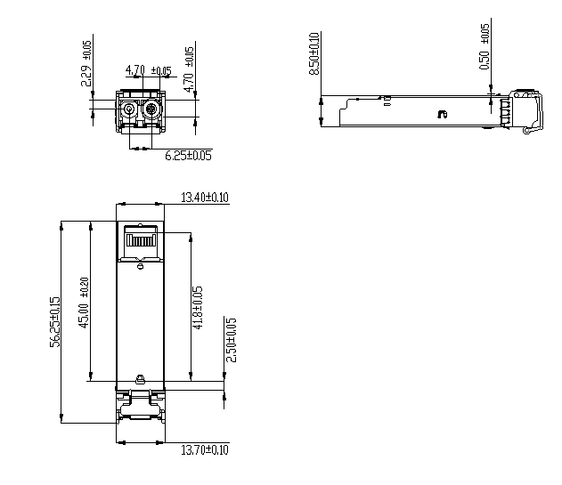
Mechanical Dimensions
Ordering Information
| Part Number | Product Description |
|---|---|
| FTCS-1312-10DIWN | SFP Transceiver, 1310nm, 1.25Gbps, LC, 10km, -40°C~+85°C, with DDM |
本产品为1.25G SFP光收发模块产品线,详细信息,请联系我们的销售人员,谢谢!
Important Notice
Performance figures, data and any illustrative material provided in this data sheet are typical and must be specifically confirmed in writing by F-tone Networks before they become applicable to any particular order or contract. In accordance with the F-tone Networks policy of continuous improvement specifications may change without notice. The publication of information in this data sheet does not imply freedom from patent or other protective rights of F-tone Networks or others. Further details are available from any F-tone Networks sales representative.