
Product Overview
The FTQ2-HG-LR4-10 is a high-performance 100Gb/s QSFP28 LR4 optical transceiver designed for data center interconnects and high-speed networking applications. It supports transmission distances up to 10km over single-mode fiber (SMF) using LAN WDM technology with four wavelength lanes.
The module integrates four 25G NRZ lanes with LAN WDM wavelengths at 1295.56nm, 1300.05nm, 1304.58nm, and 1309.14nm. It features a DFB laser array transmitter and PIN photodiode array receiver with duplex LC connector interface.
Compliant with IEEE 802.3bm 100GBASE-LR4, CMIS 4.0, and QSFP28 MSA standards, this transceiver provides a single 3.3V power supply with power dissipation below 3.5W, making it an energy-efficient solution for 100G Ethernet and OTU4 applications.

Key Features
- Compliant with 100GBASE-LR4
- Supports line rates from 103.125 Gbps to 111.81 Gbps
- Integrated LAN WDM TOSA/ROSA for up to 10 km reach over SMF
- Digital Diagnostics Monitoring Interface (DDM)
- Duplex LC optical receptacle
- No external reference clock required
- Electrically hot-pluggable
- Compliant with QSFP28 MSA with LC connector
- Case operating temperature range: 0°C to 70°C
- Power dissipation < 3.5W
- 4x DFB laser array transmitter with 4-wavelength LAN WDM
- PIN photodiode array receiver with integrated TIA
- CMIS 4.0 compliant
Applications
- 100G Ethernet & 100GBASE-LR4
- ITU-T OTU4
- Data Center Interconnects
- High-performance computing networks
Standards Compliance
- IEEE 802.3ba
- IEEE 802.3bm
- 100G LR4
- SFF-8636
- QSFP28 Multi-Source Agreement (MSA)
General Description
The 100G QSFP28 LR4 optical transceiver integrates receiver and transmitter path on one module. In the transmit side, four lanes of serial data streams are recovered, retimed, and passed to four laser drivers. The laser drivers control 4 Distributed Feedback Lasers (DFB) with center wavelengths of 1296nm, 1300nm, 1305nm, and 1309nm. The optical signals are multiplexed to a single-mode fiber through an industry standard LC connector.
In the receive side, the four lanes of optical data streams are optically de-multiplexed by the integrated optical de-multiplexer. Each data stream is recovered by a PIN photo-detector and trans-impedance amplifier, retimed. This module features a hot-pluggable electrical interface, low power consumption, and MDIO management interface.
The product is designed with form factor, optical/electrical connection and digital diagnostic interface according to the QSFP28 Multi-Source Agreement (MSA) and compliant to IEEE 802.3bm.
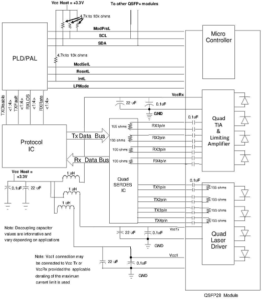
Absolute Maximum Ratings
| Parameter | Symbol | Min. | Max. | Unit |
|---|---|---|---|---|
| Storage Temperature | Ts | -40 | 85 | °C |
| Relative Humidity | RH | 5 | 95 | % |
| Power Supply Voltage | VCC | -0.3 | 4 | V |
| Signal Input Voltage | Vcc-0.3 | Vcc+0.3 | V |
Recommended Operating Conditions
| Parameter | Symbol | Min. | Typ. | Max. | Unit | Note |
|---|---|---|---|---|---|---|
| Case Operating Temperature | Tcase | 0 | – | 70 | °C | Without air flow |
| Power Supply Voltage | VCC | 3.13 | 3.3 | 3.47 | V | |
| Power Supply Current | ICC | – | – | 1060 | mA | |
| Data Rate | BR | – | 25.78125 | – | Gbps | Each channel |
| Transmission Distance | TD | – | – | 10 | km | Coupled fiber |
| Single Mode Fiber | – | – | – | – | – | 9/125μm SMF |
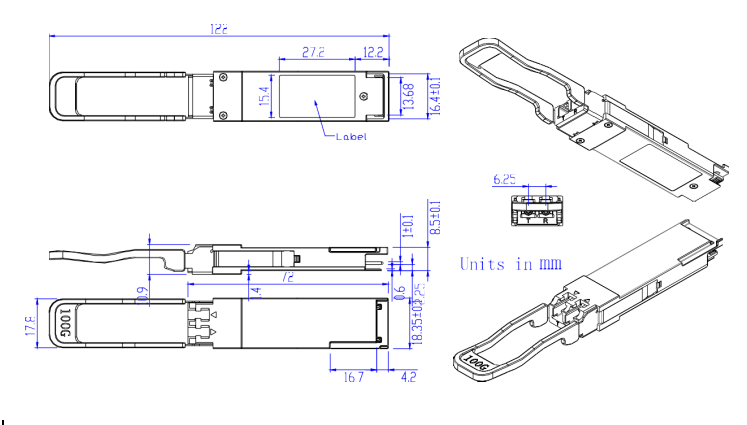
Optical Characteristics – Transmitter
| Parameter | Symbol | Min | Typ | Max | Unit | Note |
|---|---|---|---|---|---|---|
| Wavelength Assignment | ||||||
| Wavelength (LAN 0) | λ0 | 1294.53 | 1295.56 | 1296.59 | nm | |
| Wavelength (LAN 1) | λ1 | 1299.02 | 1300.05 | 1301.09 | nm | |
| Wavelength (LAN 2) | λ2 | 1303.54 | 1304.58 | 1305.63 | nm | |
| Wavelength (LAN 3) | λ3 | 1308.09 | 1309.14 | 1310.19 | nm | |
| Total Output Power | POUT | – | – | 10.5 | dBm | |
| Average Launch Power Per Lane | – | -4.3 | – | 4.5 | dBm | |
| Spectral Width (-20dB) | σ | – | – | 1 | nm | |
| SMSR | – | 30 | – | – | dB | |
| Optical Extinction Ratio | ER | 4 | – | – | dB | |
| Average Launch Power Off Per Lane | Poff | – | – | -30 | dBm | |
| RIN | RIN | – | – | -128 | dB/Hz | |
| Output Eye Mask Definition | {X1,X2,X3,Y1,Y2,Y3} | {0.25, 0.4, 0.45, 0.25, 0.28, 0.4} | – | |||
Optical Characteristics – Receiver
| Parameter | Symbol | Min | Typ | Max | Unit | Note |
|---|---|---|---|---|---|---|
| Rx Sensitivity Per Lane | RSENS | – | – | -10.6 | dBm | 1 |
| LOS De-Assert | LOSD | -30 | – | – | dBm | |
| LOS Assert | LOSA | – | – | -12 | dBm | |
| Input Saturation Power (Overload) | Psat | – | – | 4.5 | dBm | |
| Receiver Reflectance | Rr | – | – | -26 | dB |
Notes: Measured with a PRBS 2³¹-1 test pattern, @25.78Gb/s, BER<10⁻¹².
Electrical Characteristics
| Parameter | Symbol | Min | Typ | Max | Unit | Note |
|---|---|---|---|---|---|---|
| Supply Voltage | Vcc | 3.13 | 3.3 | 3.47 | V | |
| Supply Current | Icc | – | – | 1060 | mA | |
| Transmitter | ||||||
| Input Differential Impedance | Rin | – | 100 | – | Ω | 1 |
| Differential Data Input Swing | Vin,pp | 180 | – | 1000 | mV | |
| Transmit Disable Voltage | VD | Vcc-1.3 | – | Vcc | V | |
| Transmit Enable Voltage | VEN | Vee | – | Vee+0.8 | V | 2 |
| Receiver | ||||||
| Differential Data Output Swing | Vout,pp | 300 | – | 850 | mV | 3 |
| LOS Fault | VLOS fault | Vcc-1.3 | – | VccHOST | V | 4 |
| LOS Normal | VLOS norm | Vee | – | Vee+0.8 | V | 4 |
Notes: 1) Connected directly to TX data input pins, AC coupled thereafter. 2) Or open circuit. 3) Into 100 ohms differential termination. 4) Loss Of Signal is LVTTL. Logic 0 indicates normal operation; logic 1 indicates no signal detected.
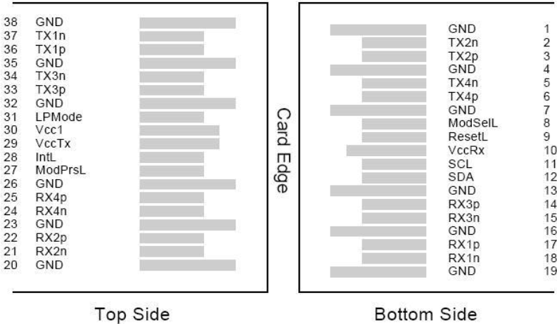
Pin Assignment
| Pin | Symbol | Name/Description | Note |
|---|---|---|---|
| 1 | GND | Transmitter Ground (Common with Receiver Ground) | 1 |
| 2 | Tx2n | Transmitter Inverted Data Input | |
| 3 | Tx2p | Transmitter Non-Inverted Data Output | |
| 4 | GND | Transmitter Ground (Common with Receiver Ground) | 1 |
| 5 | Tx4n | Transmitter Inverted Data Input | |
| 6 | Tx4p | Transmitter Non-Inverted Data Output | |
| 7 | GND | Transmitter Ground (Common with Receiver Ground) | 1 |
| 8 | ModSelL | Module Select | |
| 9 | ResetL | Module Reset | |
| 10 | VccRx | 3.3V Power Supply Receiver | 2 |
| 11 | SCL | 2-Wire Serial Interface Clock | |
| 12 | SDA | 2-Wire Serial Interface Data | |
| 13 | GND | Transmitter Ground (Common with Receiver Ground) | |
| 14 | Rx3p | Receiver Non-Inverted Data Output | |
| 15 | Rx3n | Receiver Inverted Data Output | |
| 16 | GND | Transmitter Ground (Common with Receiver Ground) | 1 |
| 17 | Rx1p | Receiver Non-Inverted Data Output | |
| 18 | Rx1n | Receiver Inverted Data Output | |
| 19 | GND | Transmitter Ground (Common with Receiver Ground) | 1 |
| 20 | GND | Transmitter Ground (Common with Receiver Ground) | 1 |
| 21 | Rx2n | Receiver Inverted Data Output | |
| 22 | Rx2p | Receiver Non-Inverted Data Output | |
| 23 | GND | Transmitter Ground (Common with Receiver Ground) | 1 |
| 24 | Rx4n | Receiver Inverted Data Output | 1 |
| 25 | Rx4p | Receiver Non-Inverted Data Output | |
| 26 | GND | Transmitter Ground (Common with Receiver Ground) | 1 |
| 27 | ModPrsl | Module Present | |
| 28 | IntL | Interrupt | |
| 29 | VccTx | 3.3V Power Supply Transmitter | 2 |
| 30 | Vcc1 | 3.3V Power Supply | 2 |
| 31 | LPMode | Low Power Mode | |
| 32 | GND | Transmitter Ground (Common with Receiver Ground) | 1 |
| 33 | Tx3p | Transmitter Non-Inverted Data Input | |
| 34 | Tx3n | Transmitter Inverted Data Output | |
| 35 | GND | Transmitter Ground (Common with Receiver Ground) | 1 |
| 36 | Tx1p | Transmitter Non-Inverted Data Input | |
| 37 | Tx1n | Transmitter Inverted Data Output | |
| 38 | GND | Transmitter Ground (Common with Receiver Ground) | 1 |
Notes: GND is the symbol for signal and supply (power) common for QSFP28 modules. VccRx, Vcc1 and VccTx are the receiving and transmission power supplies and shall be applied concurrently. The connector pins are each rated for a maximum current of 500mA.
Digital Diagnostics Functions
The FTQ2-HG-LR4-10 supports the 2-wire serial communication protocol as defined in the QSFP28 MSA, which allows real-time access to the following operating parameters: