General Description
The FTQ2-HG-ER4 is a 100Gb/s QSFP28 ER4 transceiver module compliant with QSFP28 MSA and IEEE 802.3ba. It is designed for 100 Gigabit Ethernet interfaces over single-mode fiber, supporting a maximum link length of 40km with FEC.
The module features LAN-WDM EML laser technology, duplex LC receptacles, built-in digital diagnostic functions, built-in CDR, and operates over 0°C to +70°C case temperature range. Power dissipation is less than 5W with a single 3.3V power supply.
Key Features
- Hot-pluggable QSFP28 form factor
- Supports 103.1Gb/s aggregate bit rate
- Maximum link length of 40km on SMF (with FEC)
- Power dissipation < 5W
- Built-in digital diagnostic functions (DDM)
- Built-in CDR
- LAN-WDM EML laser
- Duplex LC receptacles
- Single 3.3V power supply
- RoHS compliant
- Operating case temperature: 0~+70°C
Applications
- 100GBASE-ER4 100G Ethernet
- 100GE 4WDM-40 Applications
Pin Assignment
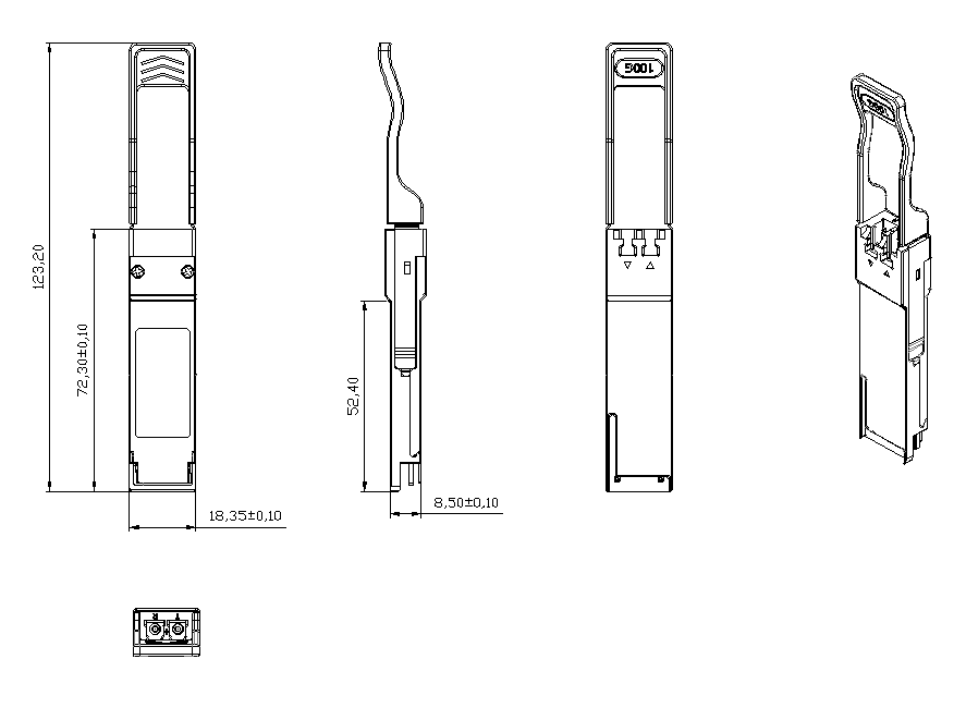
QSFP28-compliant 38-pin connector per SFF-8679.
Absolute Maximum Ratings
| Parameter | Symbol | Min | Max | Unit | Notes |
|---|---|---|---|---|---|
| Storage Temperature | Ts | -40 | +85 | °C | |
| Maximum Supply Voltage | Vcc | -0.3 | 3.6 | V | |
| Operating Relative Humidity | RH | 15 | 85 | % |
Recommended Operating Conditions
| Parameter | Symbol | Min | Typical | Max | Unit | Notes |
|---|---|---|---|---|---|---|
| Data Rate | DR | 25.78±100ppm | Gb/s | 1 | ||
| Operating Case Temperature | Tcase | 0 | – | 70 | °C | |
| Fiber Length on SMF | L | – | – | 40 | km | With FEC |
Note: Supports 100GBASE-ER4 per IEEE 802.3ba.
Pin Description
| Pin | Symbol | Name/Description | Ref. |
|---|---|---|---|
| 1 | GND | Ground | 1 |
| 2 | Tx2n | Transmitter Inverted Data Input | |
| 3 | Tx2p | Transmitter Non-Inverted Data Input | |
| 4 | GND | Ground | 1 |
| 5 | Tx4n | Transmitter Inverted Data Input | |
| 6 | Tx4p | Transmitter Non-Inverted Data Input | |
| 7 | GND | Ground | 1 |
| 8 | ModSelL | Module Select | |
| 9 | ResetL | Module Reset | |
| 10 | Vcc Rx | +3.3V Power Supply Receiver | |
| 11 | SCL | 2-wire Serial Interface Clock | |
| 12 | SDA | 2-wire Serial Interface Data | |
| 13 | GND | Ground | 1 |
| 14 | Rx3p | Receiver Non-Inverted Data Output | |
| 15 | Rx3n | Receiver Inverted Data Output | |
| 16 | GND | Ground | 1 |
| 17 | Rx1p | Receiver Non-Inverted Data Output | |
| 18 | Rx1n | Receiver Inverted Data Output | |
| 19 | GND | Ground | 1 |
| 20 | GND | Ground | 1 |
| 21 | Rx2n | Receiver Inverted Data Output | |
| 22 | Rx2p | Receiver Non-Inverted Data Output | |
| 23 | GND | Ground | 1 |
| 24 | Rx4n | Receiver Inverted Data Output | |
| 25 | Rx4p | Receiver Non-Inverted Data Output | |
| 26 | GND | Ground | 1 |
| 27 | ModPrsL | Module Present | |
| 28 | IntL | Interrupt | 2 |
| 29 | Vcc Tx | +3.3V Power Supply Transmitter | |
| 30 | Vcc1 | +3.3V Power Supply | |
| 31 | LPMode | Low Power Mode | |
| 32 | GND | Ground | 1 |
| 33 | Tx3p | Transmitter Non-Inverted Data Input | |
| 34 | Tx3n | Transmitter Inverted Data Input | |
| 35 | GND | Ground | 1 |
| 36 | Tx1p | Transmitter Non-Inverted Data Input | |
| 37 | Tx1n | Transmitter Inverted Data Input | |
| 38 | GND | Ground | 1 |
Notes:
- Circuit ground is internally isolated from chassis ground.
- IntL is an open collector/drain output, which should be pulled up with a 4.7k-10k Ohms resistor on the host board.
Electrical Specifications
| Parameter | Symbol | Min | Typical | Max | Unit | Notes |
|---|---|---|---|---|---|---|
| Power | ||||||
| Supply Voltage | Vcc | 3.135 | – | 3.465 | V | |
| Supply Current | Icc | – | – | 1.5 | A | |
| Module Total Power | P | – | – | 5 | W | 1 |
| Transmitter | ||||||
| Signaling Rate per Lane | – | 25.78±100ppm | Gb/s | |||
| Differential Input Impedance | Zin | 100 | 100 | – | Ohm | |
| Differential Input Voltage Amplitude | Vin | – | – | 900 | mVp-p | |
| Receiver | ||||||
| Signaling Rate per Lane | – | 25.78±100ppm | Gb/s | |||
| Differential Output Impedance | Zout | – | 100 | – | Ohm | |
| Differential Output Voltage Amplitude | Vout | 400 | – | 900 | mVp-p | |
| Eye Width | – | 0.57 | – | – | UI | |
| Vertical Eye Closure | – | – | – | 5.5 | dB | |
| Transition Time (20% to 80%) | Tr/Tf | 12 | – | – | ps | |
Note: 1. Maximum total power value is specified across the full temperature and voltage range.
Optical Specifications
| Parameter | Symbol | Min | Typical | Max | Unit | Notes |
|---|---|---|---|---|---|---|
| Transmitter | ||||||
| Signaling Rate per Lane | – | 25.78125±100ppm | Gb/s | 1 | ||
| Center Wavelength (Lane 1-4) | λ | 1294.53 / 1299.02 / 1303.54 / 1308.09 | – | 1296.59 / 1301.09 / 1305.63 / 1310.19 | nm | |
| Side Mode Suppression Ratio | SMSR | 30 | – | – | nm | |
| Transmit OMA per Lane | TXP | 1 | – | 7.5 | dBm | |
| Transmit Average Power per Lane | Pout | 0 | – | 7 | dBm | |
| Optical Extinction Ratio | ER | 6 | – | – | dB | |
| Average Launch Power of OFF Transmitter (per lane) | – | – | – | -30 | dBm | |
| Optical Return Loss Tolerance | RL | – | – | 20 | dB | |
| Relative Intensity Noise | RIN | – | – | -130 | dB/Hz | |
| Receiver | ||||||
| Signaling Rate per Lane | – | 25.78125±100ppm | Gb/s | 1 | ||
| Center Wavelength (Lane 1-4) | λ | 1294.53 / 1299.02 / 1303.54 / 1308.09 | – | 1296.59 / 1301.09 / 1305.63 / 1310.19 | nm | |
| Average Receive Power per Lane | RXP | -20 | – | -4 | dBm | 3 |
| Receive Power (OMA) per Lane | RxOMA | – | – | -3.5 | dBm | |
| Receiver Sensitivity (OMA) per Lane | SEN | – | – | -20.5 | dBm | 4 |
| Receiver Reflectance | Rfl | – | – | -26 | dB | |
| LOS De-Assert | LOSD | – | – | -23 | dBm | |
| LOS Assert | LOSA | -35 | – | – | dBm | |
| LOS Hysteresis | LOSh | 0.5 | – | – | dB | |
Notes:
- Transmitter and Receiver consist of 4 lasers and photodiode operating at 25.78Gb/s each for 100GBASE-ER4, Hit ratio 5E-5.
- Transmitter eye mask definition: {X1, X2, X3, Y1, Y2, Y3} = {0.25, 0.4, 0.45, 0.25, 0.28, 0.4}
- Average receive power (min) is informative. A received power below this value cannot be compliant.
- Receiver sensitivity (OMA) at 5E-5 BER is a normative specification.
Digital Diagnostic Functions
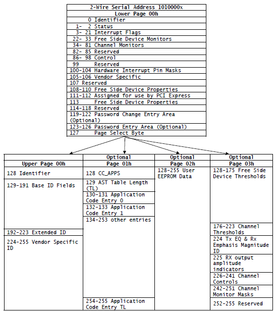
The operating and diagnostics information is monitored and reported by a Digital Diagnostics Transceiver Controller (DDTC) inside the transceiver, accessed through a 2-wire serial interface. For more information, please see the QSFP28 MSA documentation.
Mechanical Specifications
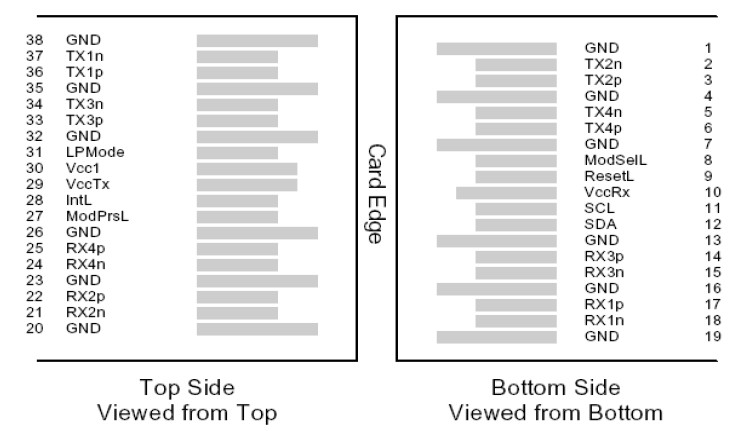
Unit: mm. QSFP28 standard form factor with duplex LC receptacles.
Ordering Information
| Part Number | Product Description |
|---|---|
| FTQ2-HG-ER4 | 100Gbps QSFP28 ER4, LC, 40km, 0°C~+70°C, with DDM |
本产品为100G QSFP28 ER4光收发模块产品线,详细信息,请联系我们的销售人员,谢谢!
Important Notice
Performance figures, data and any illustrative material provided in this data sheet are typical and must be specifically confirmed in writing by F-tone Networks before they become applicable to any particular order or contract. In accordance with the F-tone Networks policy of continuous improvement specifications may change without notice. The publication of information in this data sheet does not imply freedom from patent or other protective rights of F-tone Networks or others. Further details are available from any F-tone Networks sales representative.